Yamaha PS-3 Yamaha PS-1 |
small
analogue keyboard with accompaniment & carry case
|
 |
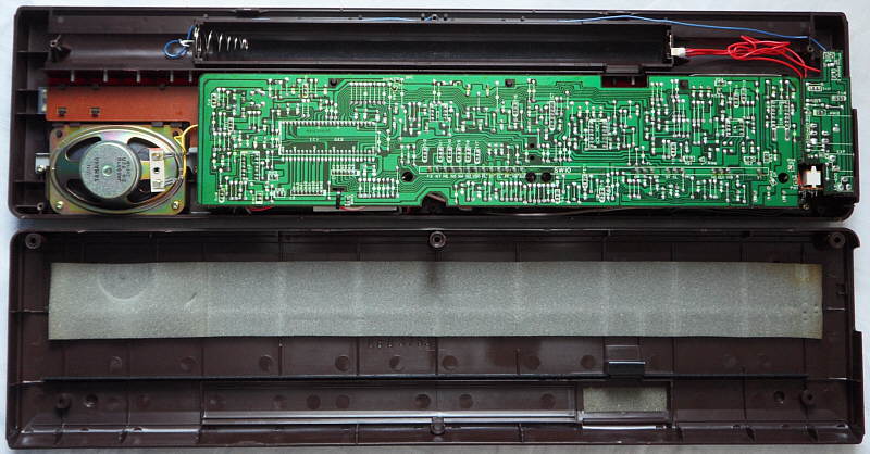
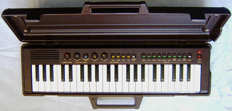
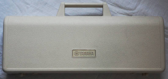
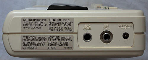
This is the instrument in its carry case. |
 |
 |
 |
 |
 |
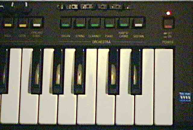 |
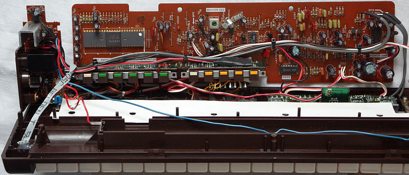
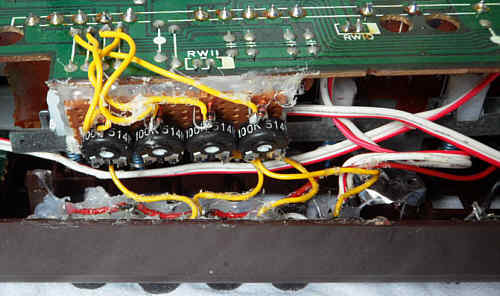
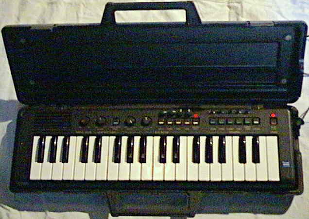
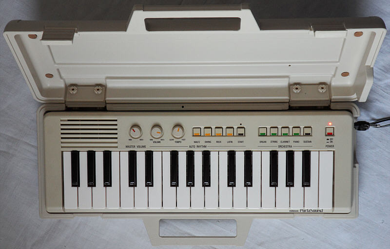
Above the buttons you see the sound knobs and switches I added. The blue thing to the right is the DIP switch block. |
All the main voice sound presets are based on squarewave with only few envelopes, those are post- processed by analogue filters and have different vibrato intensities. When a key is trilled with sustain, each new note occupies a new sound channel, which produces a great phasing sound and volume increase effect although this eats up polyphony. The "organ" resembles a reed organ o dull accordion. "string" has a bright and slightly thin violin timbre with quite strong 6Hz vibrato. The "clarinet" has the expected timbre; all these sounds employ the same simple envelope with soft attack and very short sustain. The "piano" is made from a brighter waveform (squarewave with narrow pulse width) with decay envelope and sounds a bit thin and slightly muffled; "harpsichord" is just a differently filtered variant of the latter and sounds very bright (like intended) and thin. The sustain button adds a 4s long sustain (which corresponds to the decay duration of held notes of the "piano" envelope). Since everything is analogue, the preset sound buttons also affect held notes and can be also used for live play tricks; they re-trigger held notes only when you switch from a decaying to a continuous preset sound. (However the buttons make some contact noise and don't look that robust, thus don't trill them too hard.)
The semi-analogue percussion sound quite dull, but has an unusual timbre. The base is just a dull and quiet "pop" noise (like heard in the speaker when switching a radio on) consisting of a square pulse muffled by a capacitor. The 2 tuned drums (hi bongo, hi conga) have a strange timbre between drumming on empty bottles and ceramic jugs. (Their waveform is a 5 step grainy digital sine, and both pitches can digitally overleap in fast 'latin' rhythm.) The semi- digital hihat was likely an innovation at its time and indeed sounds a bit more metallic than the analogue transistor noise ones found in other electronic percussion of that era. The single finger chord voice employs a slightly distorted organ timbre with semi-percussive attack and short sustain. Like in many historical keyboards, the automatic accompaniment plays only very short staccato chords on it to make it sound more like a piano; the bass part is a monophonic e-bass voice. The vibrato (part of "string" preset sound) also affects the single finger chord voice (by modulating the CPU clock frequency).
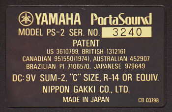
When I bought my Yamaha PS-2 on a flea market, it made always
a static beep of varying intensity in the speaker. It turned out that a
bad solder joint of an electrolytic capacitor at the voltage regulator
had caused this. After fixing it the beep was gone.
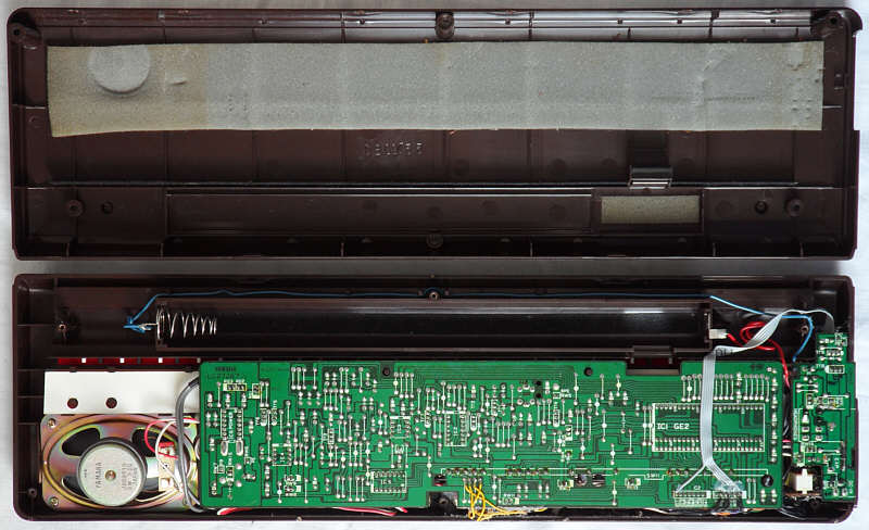
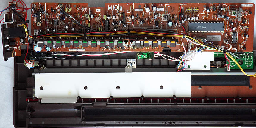
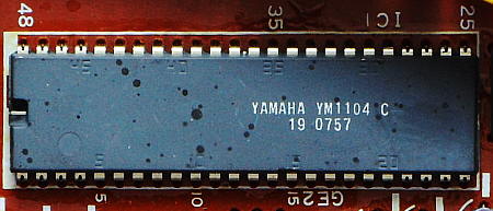
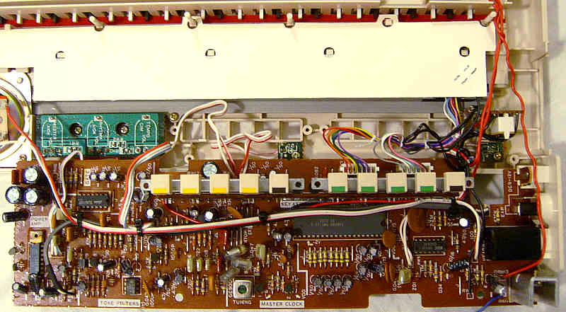
circuit bending detailsThe Yamaha PS-2 is built around the single-chip CPU "Yamaha YM1104 C" (GE2). Envelopes and fixed filters are analogue and so the PCB contains plenty of discrete circuitry and some standard analogue ICs. The power amp IC is a "Sanyo LA4188". The fullsize Yamaha PS-10 is very similar. Also Yamaha PS-3 is based on this hardware class, but has an additional VCF "Yamaha IG02611" for some of its preset sounds.
sound generatorThe CPU itself outputs only 5 internal preset raw sounds made from 2 squarewave "footages" with volume envelope, those are externally mixed and post- processed by 4 switchable fixed analogue filters to form the final preset timbres. I first thought that IC3 converts square into saw, but actually these only mix both footages. For a test connecting pins 17 and 18 with a simple 330 Ohm resistor is all it needs to transform the 'organ' raw sound into a 4 step stairwave wannabe-sawtooth. Unlike in later Yamaha instruments none of the audio outs employ a timeslice DAC. (On oscilloscope I found no chopped waveforms.)The raw sounds are an organ sound (with short attack and release envelope,
in 3 variants with different vibrato depths), a harpsichord sound (unequal
pulse wave with falling decay envelope) and a vibraphone sound (with falling
decay envelope, integrated slow vibrato and sustain always on). Sustain
decays always with the same speed. The vibrato uses an LFO pin to modulate
the pitch clock with a triangular wave.
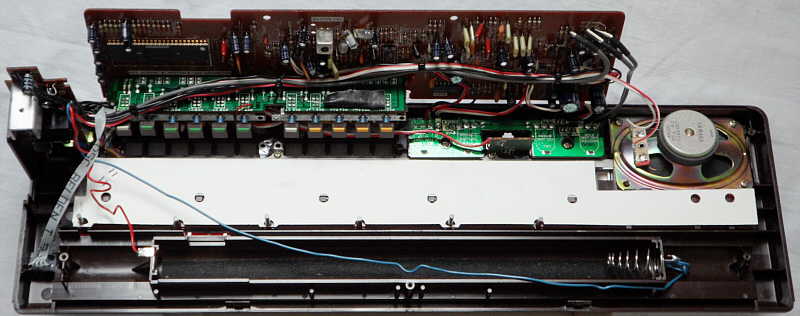
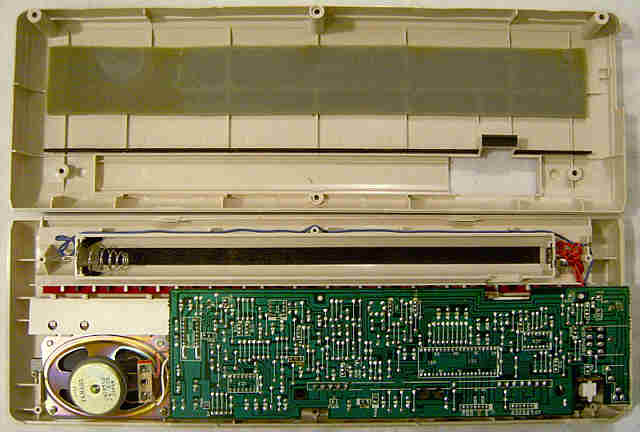
Interesting is that semi-analogue percussion has a separate clock and so stays unaffected by vibrato. The 'base' is exactly what it sounds like - namely a short digital squarewave pulse without envelope, making a pop noise like powering on an old transistorized radio. Possibly it was originally planned as a trigger pulse for an omitted analogue drum. The 'hihat' and 'snare' are made from each a semi-metallic digital waveform (likely shift-register feedback noise). The 'bongo' and 'conga' are a digital sine wave with grainy 5 step resolution (3-bit), which gives them their unique bottle clang timbre. Very unusual (slightly overengineered?) is that despite these share the same envelope cap and output, they can sound simultaneously - producing a digital waveform of 2 added sines, which sometimes blends into a kind of bottle clang timbre. (No early Casio ever did this! Also in PS-30 the caps are separate.) There are 3 envelope capacitors for 'snare', 'hihat' and 'bongo'+'conga', those can be also triggered externally (pulling lo through e.g. an 1k resistor). With the shared 'bongo' and 'conga' this will re-trigger only the one that sounded last. (They sound like an alternating whistle when envelope is clamped lo during 'latin' rhythm.) The more advanced Yamaha PS-3 employs an additional VCF (IG02611) to make 'brass' and 'guitar' grow duller over time, and in its 'vibraphone' timbre filter a VCA (IG02595, in schematics IG02602) that is fed with the vibrato LFO. The following descriptions relate to the instrument opened and placed keys facing down with view at PCB solder side. percussion pitchThe percussion pitch is controlled by a separate clock input at CPU pin 12 (independent from tempo). In Yamaha PS-2 it can be adjusted by trimmer VR2. (You may install a potentiometer here.)keyboard matrixThe keyboard matrix is grouped by 6 and has 2 cable connectors. Connector "C1" contains 6 output lines labelled N7..N2. Connector "C2" contains 7 input lines labelled {B11, B12, B21, B22, B31, B32, B41}. (The strange numbering apparently counts semi-octaves. B stands for block, N for note.) The inputs react on + 9V. Not all functions are controlled by matrix lines; e.g. the single finger chord is enabled by pulling CPU pin 46 hi. The timbre filters are directly wired to the locking preset sound switches, so the matrix only contains 5 raw basic sounds. In Yamaha PS-2 the 'vibraphone' is an unused easteregg. This keyboard matrix was analyzed by me.
The input lines are active-high, i.e. react on +Vs. Any functions can
be triggered by a non- locking switch in series to a diode from one "out"
to one "in" pin.
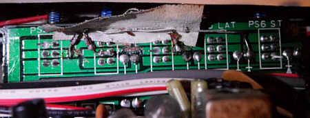
additional keysAt CPU pins 38, 39 exist unused matrix places to connect 7 higher note keys (wired through diodes against pins N2..N7 of connector "C1").additional combined rhythmsIn Yamaha PS-10 multiple rhythm buttons can be pressed simultaneously to produce 11 additional combined rhythms (concluded from schematics photo). Unfortunately the rhythm switches in PS-1, PS-2, PS-3 are wired the same way in series like the sound presets, thus when multiple buttons are pressed, only the rightmost one will activate a keyboard matrix line because opener contacts deactivate all switches left to it. Technically they simply connect CPU pins N4..N7 through each a diode to P2. By cutting the traces to the 2 center pins of each switch and connecting the center pins instead through a diode (anode at the switch) with the 2 center pins of the "start" button (= CPU pin 3), the limitation is overcome.rhythm start switchInstead of synchro start, also a normal rhythm start switch can be wired through a diode from CPU pin N3 to P2. Like in Yamaha PS-1 it runs rhythms simply so long it is on (without wait for key press).tekkno noisesConnecting the keyboard matrix input B11 through a diode with outputs N5..N2 makes various strange and rough crash sounds. (I guess that here either a 2nd CPU could communicate with the CPU in costlier instruments, or this was simply a test mode. In the service manual these 4 matrix places are in brackets, but still have lower note names corresponding to their position, so possibly even the author did not know what they do.) After releasing, the program always continues running as before (i.e. doesn't hang). One of these inputs even pitches the entire instrument (including drums and accompaniment) by 1 octave up. I have wired a 4 DIP switch block to these.timbre synthesizer & distortionIn Yamaha PS-2 originally each sound preset switch selects one of only 3 squarewave raw sounds (different pulse widths and envelopes) and by another contact one of 4 analogue filters to set its timbre. The switches are wired in series in a way that when multiple buttons are pressed, only the rightmost one will take effect because additional opener contacts in each switch disconnect all switches left from it.filter controls: Each switch has 6 pins. At the leftmost switch "PS7OR" (organ) the 2 top pins are unused. For manual filter controls, connect the left upper pin of switch "PS7OR" with 4x parallel [a 100 kOhm trimmer in series with a 10 kOhm potentiometer (wired as variable resistors: wipers as output, left ends unused) and its wiper connected with the anode of a diode]. Connect the other ends of these diodes with the filter control pins X1, X2, X3 and X5. These are located at the left end of the button PCB; there are 5 pins in a row those I referred in my scribbled schematics as X5..X1. (I don't remember well if these numbers are printed on the PCB or if they were by me, but I think they were printed.) These inputs select through a 4066(?) IC 4 different analogue filters those modify the raw sounds. By space reasons it is recommended to use trimmers with capstan instead of normal size 10 kOhm potentiometers.
raw sound switches: The raw sounds are selected by connecting the "C1" outputs N2 to N6 through a diode with pins 2 of the CPU:
This way it becomes possible to select the new timbre synthesizer feature by switching all preset sound buttons off (push one button halfway in to release them). Now you can combine any of the 5 raw sounds with any combinations of the 4 filters. Adjust the 100 kOhm trimmers in a way that each filter can be as well fully enabled as fully disabled by its potentiometer. The analogue filter selection IC (a 4016) distorts greatly when pots are only halfway open, which is especially noticeable during main voice chords. By selecting any sound preset, the timbre synthesizer will be disabled automatically, because electrically it behaves now simply like another preset switch left to the "organ" one. (Attention: My handwritten schematics of this modification are quite old, messy and incomplete, thus I can not guarantee that the above instructions are fully correct.) important: According to the service manual, only in Yamaha PS-2 and PS-1 the output of the fixed timbre filters is routed through each an analogue switch in the IC 4016 "orchestra gate" (IC5 in PS-2, IC3 in PS-1) to the mixing amp, when the corresponding preset sound switch is set. But in PS-3 the timbre filter outputs are wired directly (without IC) through each one of those switches to the mixing amp, hence the timbre behaviour of added potentiometers will likely differ. The PS-1, PS-2 and PS-3 hardware design appears
to be a cheapened and specialized variant of a more general hardware platform
(already used 1979 in the Electone CN-70 organ) that later became
Yamaha
PS-30 and PS-20.
E.g. the lack of matrix pin "N1", footage naming irregularities (varying
pulse width among raw sounds) and the digitally mixed bongo and conga 3-bit
sinewaves (a 3-bit DAC supports 8 steps, hence 3 drums like found in PS-30)
strongly hint to this.
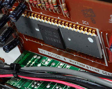
pinout YM1104 (GE2)The 8 Tone Generator "Yamaha YM1104" (48 pin DIL) is the GE2 single chip CPU of the first PortaSound keyboards Yamaha PS-2, PS-3 and the fullsize PS-10.Technically this is likely an ASIC made from logic gates with little software control. It contains an 8 note polyphonic sound generator (4 of them can be re-routed as bass & chord voice of single finger chord & accompaniment) with each an envelope capacitor out. Each main voice outputs 2 squarewave footages those have to be mixed and filtered by external analogue circuits. The semi-analogue percussion generator employs digital semi-metallic snare and hihat waveforms and 3-bit sinewaves for bongo + conga, using 3 envelope capacitors. The CPU controls a keyboard matrix with 9 inputs and 6 outputs, supporting 44 keys. A vibrato pin modulates the main voice oscillator, so a separate rhythm clock pin keeps percussion unmodulated. Early versions of this CPU ("Yamaha YM1 104 C, 14 0455" in my PS-2) had an expensive looking unusual shaped grey ceramic package with white rim and golden pins; the square black label plate above the die protrudes higher than the rest. Later versions ("Yamaha YM1104 C, 19 0757" in my PS-3) had normal shape with silver pins, plain grey ceramic and some embossed pin numbers. This pinout was based on a badly blurred schematics photo fragment of the Yamaha PS-10 service manual. So I measured the functions by myself and partially corrected names by conclusions from my Yamaha PS-20 service manual. Later I found the real Yamaha PS-1, PS-2, PS-3 service manual and fixed misspelled pin names. caution: The schematics suggests that this CPU uses "negative
logic", i.e. technically +9V is its GND while 0V is its -9V supply voltage.
So the voltages are not was the pin names suggest. I use the positive
voltage naming convention (from 0V to +9V, not -9V to 0V).
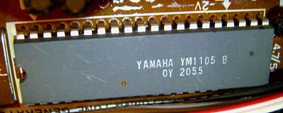
In the keyboard matrix are 4 "strange mode" places those double main voice and percussion pitch or totally mess up main voice and percussion. Likely this was either a test mode or even turns keyboard matrix lines into a data port to control the YM1104 as a sound IC by a host CPU. AFAIK no keyboard or home organ did this. Despite the strange noises, the chip keeps running after turning it of. It is hard to crash, which hints that it is very little software controlled and has barely any RAM (only registers for rhythm counter, envelopes and currently sounding single finger chord). The presence of multiple clock inputs and envelope capacitors (internal VCA) shows that this is no standard microcontroller. Also by its age I suspect that this is likely an ASIC purely made from logic gates. Unlike in later Yamaha keyboards, at none of the audio outs I found hints to a timeslice DAC. There is only some HF dirt those are likely clock and internal data residues. Very unusual is that despite bongo and conga share the same audio out pin and envelope capacitor pin, their digital waveforms (5 step sine) can overleap into a mix of both pitches when at fast tempo setting both drums are still sounding. I never found this type of polyphony in other keyboards with shared capacitors for semi-analogue percussion. The tempo potentiometer controls a clock frequency fed to pin 4. The vibrato pin 8 outputs a triangular wave to modulate the main voice oscillator pin 48 (falling sawtooth, period about 2.2us on oscilloscope (= 455 kHz), real clock in service manual is 530 kHz). Holding a 10nF capacitor to GND at it produced siren-like or stuttering chaotic howl, because it badly messed up keyboard scanning and envelope generator. I suspect that it ran too far out of sync with other clock pins, because unlike in most newer keyboards, this IC has separate inputs for percussion clock (pin 12, period about 5us = 200 kHz) and rhythm tempo oscillator (pin 4) to avoid their unwanted modulation by vibrato. According to schematics, in PS-3 the LFO additionally modulates the VCA amplitude of the 'vibraphone' timbre filter. Pin 29 outputs a short hi pulse during each additional melody voice key press (also when others are held). No pulse is produced by chord or accompaniment notes, or when no preset sound is selected. This signal is used in Yamaha PS-3 to trigger its VCF envelope in certain preset sounds. A cheapened variant of this CPU was the YM1105 found in Yamaha PS-1. |
A fullsize variant of this hardware was released as Yamaha PS-10 (44 keys, 6 preset sounds, combinable 4 preset rhythms, case like PS-20).
 |
 |
Many preset sounds correspond to the PS-2,
so I only explain the additional ones. The "flute" is a duller variant
of "clarinet" with little vibrato. "brass" employs a oboe- like timbre
with little vibrato and grows duller within 1 second by the VCF envelope;
it has barely similarity with brass instruments but rather with woodwinds;
the bass range is rather bright and hollow, while high notes sound flute-like.
"guitar" is a bright variant of "piano" that employs the VCF to grow duller;
it may resemble a steel string guitar or banjo, but high notes rather resemble
a koto or steel drum. The "vibraphone" is made from a dull squarewave timbre
(same like "flute"?) with 5s long decay envelope and very strong 4Hz vibrato
(and tremolo?); it always enables sustain and ignores the sustain switch
setting.
hardware detailsThe Yamaha PS-3 hardware strongly resembles PS-2, but contains the additional VCF "Yamaha IG02611" and VCA "Yamaha IG02595".
The Noystoise website did a complete redesign of Yamaha PS-3 into a very impressive Minimoog-like synthesizer, including DIY schematics and some hardware analysis. E.g. he found out that the VCF chip IG02611 is pin compatible with the IG02610 of Yamaha CS01, and also the VCA was used in many analogue Yamaha CS-series synths. |
 |
 |
 |
 |
circuit bending detailsThe Yamaha PS-1 is built around the single-chip CPU "Yamaha YM1105 B" (GE1). Envelopes and fixed filters are analogue and so the PCB contains plenty of discrete circuitry and some standard analogue ICs.
sound generatorThe melody voice generator of CPU YM1105 in Yamaha PS-1 surprisingly differs from the YM1104 of PS-2 and PS-3. Instead of 2 footages it outputs only a single squarewave, which however has more different pulse widths.
keyboard matrixThe keyboard matrix layout is basically the same like in Yamaha PS-2, but lacks 6 higher note keys and does not support 'synchro start'. Also here the timbre filters are directly wired to the locking preset sound switches, so the matrix only contains 5 raw basic sounds. Despite on the PCB pin B41 is on connector C1, it seems to be unused. Possibly initially a 37 keys version was planned but not made.
The input lines are active-high, i.e. react on +Vs. Any functions can
be triggered by a non- locking switch in series to a diode from one "out"
to one "in" pin.
The preset sound and rhythm switch wiring correspond to Yamaha
PS-2, thus certainly similar modifications can be done. Interesting
is that the 'strange mode' matrix places sound different (e.g. can not
switch the main voice octave), which hints that both CPUs are indeed internally
different.
pinout YM1105 (GE1)The 8 Tone Generator "Yamaha YM1105" (40 pin DIL) is the GE1 single chip CPU of Yamaha PS-1.It is very similar like YM1104 (see there), but lacks all chord and accompaniment features, supports only 38 keys and the melody voice has only a single squarewave output instead of 2 footages. Initially I expected it to be simply a cheapened package variant of YM1104 with fewer pins, but the very different pin order and subtle behaviour differences (lacks 'synchro start' feature, different main voice pulse widths) makes me conclude that the chip itself is different. Thus I describe it separately. This pinout was concluded from badly blurred schematics photo fragment of the Yamaha PS-10 service manual and my own comparison between Yamaha PS-1 and PS-3. Later I found the real Yamaha PS-1, PS-2, PS-3 service manual and fixed wrong pin names. caution: The schematics suggests that this CPU uses "negative
logic", i.e. technically +9V is its GND while 0V is its -9V supply voltage.
So the voltages are not was the pin names suggest. I use the positive
voltage naming convention (from 0V to +9V, not -9V to 0V).
Generally the audio signals of YM1105 seem to have more HF dirt or noise than in YM1104. This may have to do with fewer separate voltage and ground pins for its analogue part. (No, this is not a timeslice DAC.) E.g. the melody out pin 22 on oscilloscope looks much fuzzier than the 2 separate pins in Yamaha PS-3. The noise may also come out of the connected op-amp. (I haven't desoldered it for exact comparison). The audio output of that op-amp looks clear enough but is obviously highpass filtered (warped squarewaves) and inverted. |
Technically a direct successor of this instrument was the fullsize
Yamaha
PS-20, which had a more complex accompaniment, arpeggio and 8 rhythms.
Already in 1982 Yamaha abandoned the analogue technology entirely
and thus made all following PortaSounds (e.g. PC-100)
only with strictly digital sound generation, while Casio kept analogue
percussion and filters in their instruments far longer until the mid of
1980th. Despite their age, the Yamaha PS-1, PS-2 and PS-3
are not really rare and still occur from time to time on eBay.
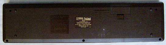
| removal of these screws voids warranty... | ||
 |
||
|
|