Musical calculators belong to those early one-chip-wonders, those first time integrated different things like calculator, alarm clock, calendar, stopwatch, music box and organ into a single small device, and so constitute an early example of technological convergence. And unlike nowadays self-combusting smartphones they managed to do all this with extremely low power consumption (and miniscule EMF emission), because these highly optimized systems got by on a tiny 4-bit CPU with often less than 33 kHz.
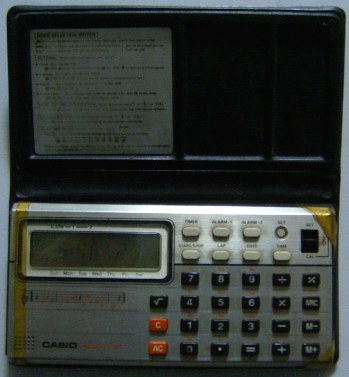
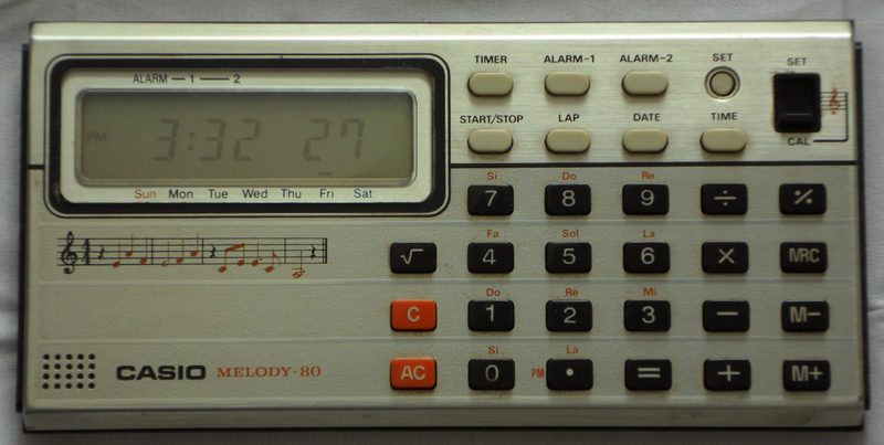
This little instrument of 1979 was Casio's first musical calculator. Unlike later models, the timbre is a rough squarewave piezo beep (resembling bagpipes) with a crude sort of square tremolo, i.e. the buzzy tone is interrupted by short pauses 4 times per second, which resembles a purring stutter dial tone of US phone service or tabletop electronic games of its era. 11 of the buttons act as note keys, and it has 3 melodies for alarm clock and timer. The sounds of it were obviously used in the sci-fi TV series "Buck Rogers" and "Battlestar Galactica".
The original box shows the alternative name "ML-80" (seen on eBay) which is not on the calculator itself. The original retail price in a Californian ad of 1979 was 49.50$.
 |
 |
Also calculator results are played as a note sequence (cipher by cipher from left to right). In combination with e.g. a repeated squareroot or constant function (press an operator button twice, e.g. "1 ++ 1" makes it add 1 and hence count with every further press of '=') this forms a simple composing algorithm that is interesting for experimental music. This mode exists in most later Casio musical calculators, but not in VL-series. The error sign 'E' plays a higher note. Other buttons play a blip.
Typical for Casio, the calculator features date calculation, i.e. you can type a date (enter 3 2-digit numbers separated by 'date') or use that of today (press 'date') and add or subtract a number of days to it (even repeated as constant). You can even store a date in 'M+' memory. (Dates do not playback as notes but only blip.) Multiply or divide by a date causes error, percent or squareroot of date does nothing. I first thought the algorithm wasn't Y2K-proof, i.e. this calculator was so so much ahead of its time that since year 2000 the day of the week indicator showed the day of tomorrow. But on a website I found the tip to enter the year as 4 digits (accepts from 1901 to 2099), which does the trick and now it's correct.
Although not actually keyboards, musical calculators were Casio's origin
of inventing VLSI chip based musical instruments. This makes them historically
important to document their hardware - not least to understand the concepts
and technical tricks behind the inner working of early related mini keyboards
like
Casio VL-1. It is hard to
find exact info about release dates, because calculator collectors websites
have contradicting entries and often seem to insert "1980" or "1985" by
default when they don't know the exact date.
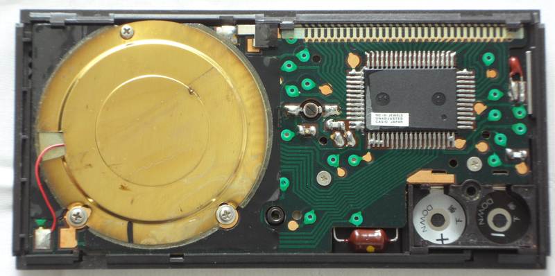
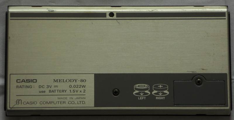
hardware detailsThe Casio Melody-80 is based on the CPU "NEC D1863G" (crystal clocked, likely at 32.768 kHz).
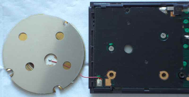
The general principle of musical calculators (playing notes during simultaneous number entry) is described in Casio patent US4294154. Apparently the concept originated from giving auditory feedback to e.g,. visually impaired people (much like a talking calculator) because the text describes an older mode that only sounded as many notes as digits fit on the display. The digital tone generator (has no envelope) with alarm sound and calculation result playback is described in Casio patent US4336598. A more sophisticated version of the Casio calendar algorithm is detailedly explained in patent US4274146 (all with priority date 1978). The general idea of a calculator with clock existed already in 1972 (priority date of patent US3813533). note: To open the case correctly, first remove battery lid and center screw at case bottom. Then slide the bottom to the right and lift it off. Do not pry; it easily disengages when pushed sideways. Do not remove the PCB if avoidable; it is next to impossible to safely reinstall it without damaging the LCD foil cable, because it always gets pinched at the upper case rim. The LCD is held inside the case by a sheet metal cover with tabs at its left side. The PCB is held by additional screws under the speaker. Caution!: The LCD foil cable is fragile. Never pull at it (it may snap off) nor sharply fold it (carbon traces crumble off). Handle it with extreme care. (If the cable comes loose at an end, install an adhesive foam rubber strip to press it on.) The right end of the LCD metal frame must be inserted under the plastic rim, then the left end carefully pushed down to engage with the plastic tabs. Never attempt to reinstall the PCB by force with improperly inserted LCD. I had to take the PCB out and remove black foil to take photos. Despite I was this time really careful (I had previously ruined the cable in ML-81) it was impossible to reinsert it without damage, because the foil cable by poor design always gets pinched at the upper rim, which resulted in partial loss of the rightmost 2 digits. Fortunately they recovered after tightening PCB screws and waiting some minutes to let the mangled foil expand back into its natural shape. test modes Pulling pin 64 hi switches the keyboard into a test mode, that while connected disables normal keyboard inputs and instead makes each button change the behaviour of various internal timers while pressed. The realtme clock changes also affect the stopwatch.
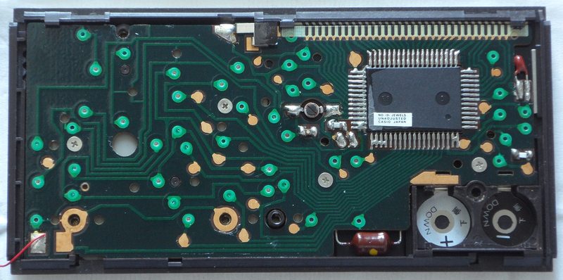
Pulling pin 63 hi enters another test mode which stops a sounding tone and does more irregular glitch things during button press. Likely this writes garbage data into ram, depending on button presses. During both test modes I observed fast data pulses on matrix out pins. keyboard matrixThe keyboard matrix of this monophonic instrument has no diodes. The only 4 input lines hint to a simple 4-bit architecture. The only easteregg is another clock mode, and the '+' doublet at 14->8 sounds no blip. First I got puzzled by many doublets and thought this matrix was much more complicated, but it turned out that they were only result of the slide switch shorting pin 7, while the rest is mostly identical with ML-81.Like in all later Casio musical calculators (Sharp too),
the matrix scanning algorithm starts a note when a 1st key button is depressed
and then simply ignores everything else (i.e. holding multiple buttons
keeps that first note sounding) until all buttons are released,
which prevents fast play and particularly the intuitive use of multiple
fingers. Only in VL-series (see VL-1)
the algorithm got changed to properly respond on a 2nd finger.
The input lines are active-high, i.e. react on +Vs. Any functions can
be triggered by a non- locking switch in series to a diode from one "out"
to one "in" pin. The mode switch is locking and selects 'calculator' when
open.
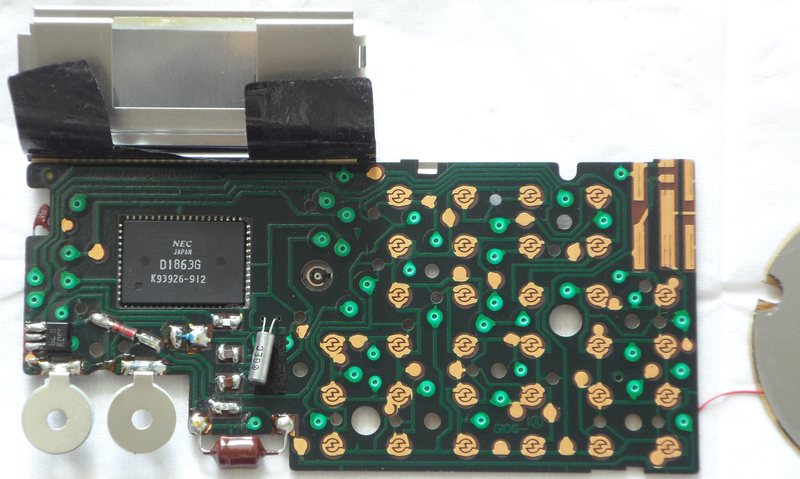
Connecting pins 7->8 switches to clock mode. I suspect that this was intended as a 4th place of the mode switch. The behaviour resembles 'M. set' (at 7->10) but does not show the AM/PM segments when pressing '.'. pinout D1863GThe "NEC D1863G" (64 pin SMD, pins count anticlockwise from the lower left) is the 4-bit CPU of Casio's first musical calculator with clock. It supports a segment LCD (31 pins) and a keyboard matrix with 9 outputs and 4 inputs. The monophonic plain squarewave (1:1) tone generator has no envelope and outputs a normal and inverted (not used) version that was likely planned to be uses for a bipolar amplifier. (In the actual device it drives the piezo speaker with parallel inductor through a single transistor amp.)(Important: Because the CPU is here soldered upside-down to the
PCB, count the pins clockwise from lower right. By lack of schematics,
all pin names were choosen by me - inspired by the naming convention of
the D1867G in Casio
VL-1. That CPU uses "negative logic", i.e. technically +3V is its
GND while 0V is its -3V supply voltage. So the voltages are not was
the pin names suggest. I use the positive voltage naming convention
(from 0V to +3V, not -3V to 0V).)
Beside the lack of envelope generator and 2 less keyboard matrix outs, this CPU is almost identical with the successor D1864G of ML-81. The clock rate estimated on my analogue oscilloscope is like ML-81, so I suspect the genuine frequency to be 32.768 kHz, which is typical for quartz clocks. The tone pitch howls down when the attached clock trimmer is shorted by fingers. Touching or shorting clock pins produces plenty of strange glitch and crash sounds, including rhythmical beeps (like a non-melody alarm clock) and strange modem noise. But the observed behaviour is less bizarre than the R2D2 glitch of my ML-85 and likely can be triggered the same by wiggling the open battery lid. The CPU pins 1, 20, 59..61 are NC (internally not connected); they have high resistance, no reverse diode and also finger hum on oscilloscope does not change waveform contact with the probe. Hence 1 and 20 were connected only to ease trace routing. Unlike D1864G also pins 17, 18, 19 (I desoldered 16, hoping to find strange DAC bit stuff with omitted resistors) are high resistance with neither output nor reverse diode behaviour, hence NC and only wired to reach 16. Pin 58 is internally connected to supply voltage pin 26. The LCD display signals are made from 4 voltage levels and work like in ML-81. With low battery (2.66V) the LCD reference voltage pin 21 has 0.89V and pin 25 has 1.68V. Unlike D1864G the audio out pin 16 goes lo when idle. The (here unused) inverted pin 15 is hi like there. Pins 63 and 64 are test pins and make interesting glitches (see above) when pulled hi. Pulling 64 hi makes pins 2, 3, 4, 5 output bursts of digital HF pulses (likely data) while other matrix outs stay lo. Pulling 63 hi shows on all matrix out pins a steady stream of data (can not be triggered on my analogue scope). The 4-bit hardware has likely 16 characters {"0".."9", space, "-", "A", "E", "L"} with one of them unused. |
The direct successor of this calculator was Casio
ML-81 (different sound).
| removal of these screws voids warranty... | ||
 |
||
|
|