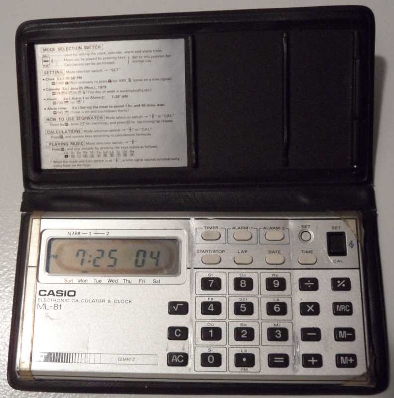
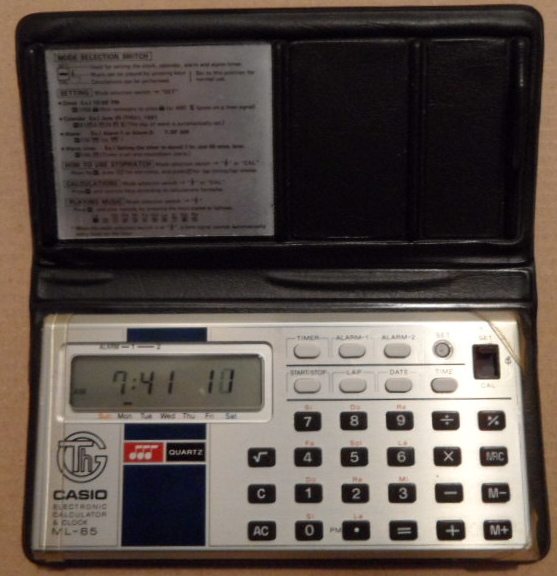
Most unique of this model is that the stopwatch 'start/stop' button also acts as 'one key play', i.e. in calculator mode it can not only playback calculation results as notes, but you can at any time manually step through the currently displayed number (up to 8 ciphers, including '.', '-' and 'E' sign) as musical notes (which does not interfere with calculation or entering further ciphers). At the end the sequence starts from beginning, so you can loop through it in your own tempo (hold notes etc.), which in combination with calculator functions (memory, squareroot etc.) makes a nice experimental composition tool.
The ML-81 was later re-released as Casio ML-85. Due to strong similarities I only describe here the differences to Melody-80.
 |
 |
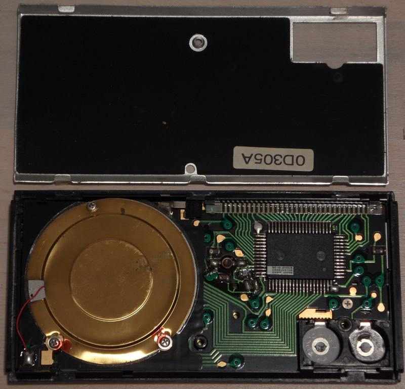
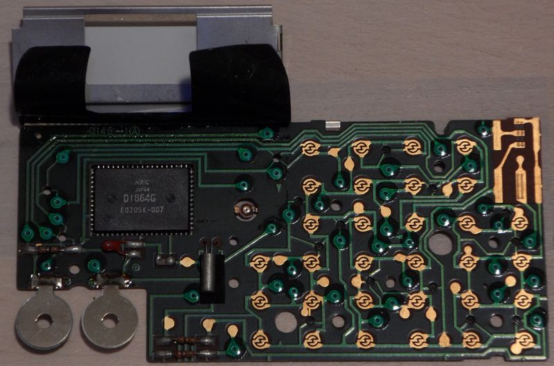
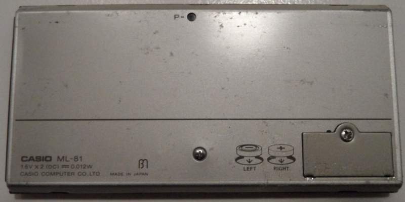
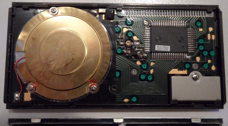
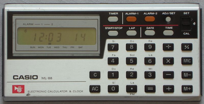
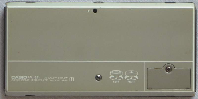
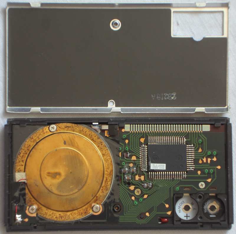
hardware detailsThe Casio ML-81 is based on the CPU "NEC D1864G" (crystal clocked, likely at 32.768 kHz), which directly drives the piezo speaker. My ML-85 seems to have the same PCB; I only saw its back and so couldn't verify the CPU type. It lacks the reset capacitor and a serial resistor of the crystal, thus shitshot makes it crash much more spectacularly by chaotically fluctuating clock speed (see here). My ML-88 additionally lacks the clock trimmer; after battery insertion it often runs 4x too fast and keys don't work (only slide switch) until I press reset.
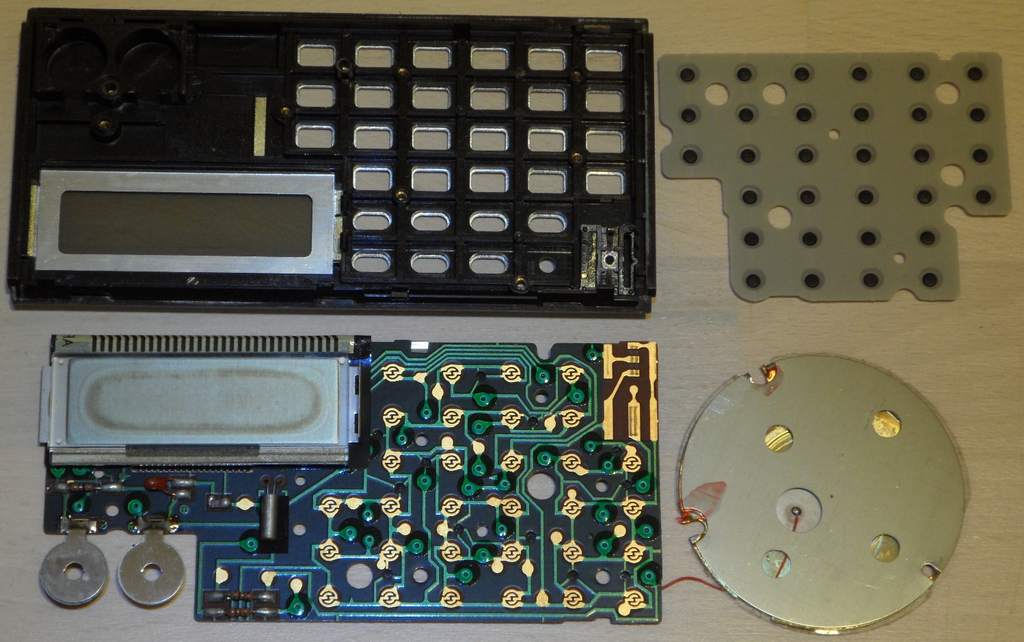
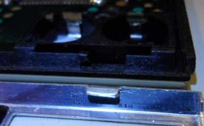
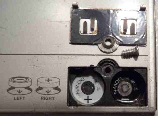
Do not remove the PCB if avoidable; it is next to impossible to safely reinstall it without damaging the LCD foil cable, because it always gets pinched at the upper case rim. The LCD is held inside the case by a sheet metal cover with tabs at its left side. The PCB is held by additional screws under the speaker. My LCD reflector was decomposed brownish (likely by UV damage), so I wanted to replace it with aluminium foil adhesive tape, but when I peeled it off, also the rear polarizer foil came off and crumbled apart (it makes no picture without), so I scraped off the residues (using a cable tie piece and finger nail) and successfully replaced it with the silver LCD back foil from a broken cheap databank calculator. Caution!: The LCD foil cable is fragile. Never pull at it (it may snap off) nor sharply fold it (carbon traces crumble off). Handle it with extreme care. (If the cable comes loose at an end, install an adhesive foam rubber strip to press it on.) The right end of the LCD metal frame must be inserted under the plastic rim, then the left end carefully pushed down to engage with the plastic tabs. Never attempt to reinstall the PCB by force with improperly inserted LCD.
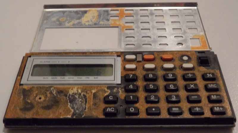
The ML-88 is slightly different inside. The foil cable may be narrower (I still refused to take the PCB out) and the plastic under the outer metal shell (mine was loose, so I reglued it with double sided adhesive tape) has no hole for the omitted squareroot button (but the keyboard matrix recognizes it as an easteregg). In my specimen the speaker cable was broken at the PCB (by battery acid vapours?), so I resoldered it. test modes Pulling pin 64 hi switches the keyboard into a test mode, that changes the behaviour of melody playback during button press.
Pulling pin 63 hi enters another test mode which stops a sounding tone and does more irregular glitch things during button press. The 'timer' and 'alarm-2' buttons sound a continuous tone with the pitch (and previous volume step?) of the last played note. Pressing them again makes the volume increase by each one step (7 in total) and return to 0 (silence), which was likely made for DAC testing. Releasing pin 63 (lo again) does irregular glitches. Likely this writes garbage into ram, so it simulates random button presses (by keyboard buffer?) or the melody plays at half tempo after this. During both test modes I observed fast data pulses on matrix out pins. keyboard matrixThe keyboard matrix of this monophonic instrument has no diodes. The only 4 input lines hint to a simple 4-bit architecture. The only eastereggs are a tone scale jingle and another clock mode. Beside the slide switch part, the matrix layout is identical with Melody-80, but the '+' doublet at 14->9 here does its normal blip tone.
The input lines are active-high, i.e. react on +Vs. Any functions can
be triggered by a non- locking switch in series to a diode from one "out"
to one "in" pin.
Wiring a button from pin 7 to any of the 4 inputs sounds an ascending tone scale (8 full notes). Unlike other melody buttons {timer, alarm-1, alarm-2} this does not change display contents in any way (when e.g. in the middle of a calculation). I suspect this was either a test feature or designed to be wired to the mode switch in a way that the music mode in other models can start with it. Interesting is that the technically very different Casio PT-82 also starts with this jingle.
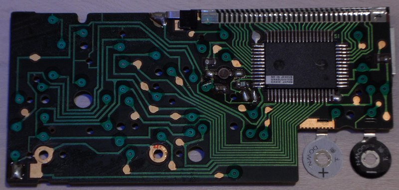
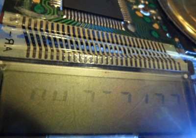
Connecting pins 18->8 switches to clock mode. Unlike the 'time' button (at 12->8) this plays the tone scale jingle when in music mode. I suspect that this was intended as a 4th place of the mode switch. The behaviour resembles 'M. set' (at 17->9) but does not show the AM/PM segments when pressing '.'. pinout D1864GThe "NEC D1864G, ...-xxx" (64 pin SMD, pins count anticlockwise from the lower left, xxx = software number of internal ROM?) is the 4-bit CPU of Casio musical calculators with clock. It supports a segment LCD (31 pins) and a keyboard matrix with up to 11 outputs and 4 inputs. The monophonic plain squarewave (1:1) tone generator has digital decay envelope (7 steps = 3-bit DAC). Through an internal bipolar amplifier it can directly drive a piezo speaker.This CPU is almost identical with its predecessor D1863G of Melody-80, but has an envelope generator and uses 3 additional pins for 2 keyboard matrix outs and audio trigger out. (Important: Because the CPU is here soldered upside-down to the
PCB, count the pins clockwise from lower right. By lack of schematics,
all pin names were chosen by me - inspired by the naming convention of
the D1867G in Casio
VL-1. That CPU uses "negative logic", i.e. technically +3V is its
GND while 0V is its -3V supply voltage. So the voltages are not was
the pin names suggest. I use the positive voltage naming convention
(from 0V to +3V, not -3V to 0V).)
The clock rate estimated on my analogue oscilloscope is about 27.8 kHz. I suspect the genuine frequency to be 32.768 kHz, which is typical for quartz clocks. My ML-85 and 1st ML-90 lacks the reset capacitor at pin 62 and the serial resistor of the crystal, hence this CPU likely works well enough without. The tone pitch howls down when the attached clock trimmer is shorted by fingers or battery drains (seen in my 2nd ML-90). My ML-85 often does really spectacular bizarre crashes during this shitshot, those partially sound such blatantly of R2D2 (the Star Wars robot), that I suspect that George Lucas may have been inspired by recordings of this. It also displays strange running counters or the seconds of the clock run at either tremendous speed or digits step up by a different amount than 1 (which makes me conclude that the internal counter uses the CPU single-digit addition of the calculator, that like the constant function can repeatedly add any number). This phenomenon also exists in some other Casio melody calculators and the melody alarm clock MA-1. So my 1st ML-90 (from childhood, serial sticker "0D308A") after battery insertion basically always starts in this mode until I press reset. This may mean that there is much software control involved, but it also could be simply result of simultaneous activation of gate logic circuits those were designed to be mutually exclusive. The piezo speaker here sometimes outputs modem-like creaky noises or squarewave tones with noise floor. Examining the situation closer with my analogue oscilloscope at the right crystal pin reveals that the clock frequency apparently runs freely in a kind of chaotic oscillation, exciting overtones of the crystal at partially about 250 kHz (i.e. 9 times too fast, very low amplitude), which randomly fluctuates back into a triangular wave of about 1.5 times the normal clock rate. It is hard to say why it toggles between at least 2 frequencies. It may be either a pure oscillator phenomenon, or the overclocked crashing software repeatedly writes to a clock speed change or reset register that fails to restart because the resulting clock reset pulse is output too short. Touching the left quartz pin with the scope probe always forces the quartz back to normal speed (a sine with higher amplitude). The R2D2 glitch in ML-85 happens only with full batteries and apparently depends on the omitted serial resistor of the crystal; in my ML-81 such noises can be triggered only while shorting CPU clock pins 22 with 23 directly (bridging the 703k resistor), but removing the short immediately returns to normal clock rate, thus likely the serial resistor needs to be bridged/removed to stay in R2D2 mode. In both models this glitch can not be triggered by power shitshot (e.g. wiggling the battery lid). My ML-88 additionally lacks the trimmer and after battery insertion often runs 4x too fast (keys don't work). Shorting both crystal pins seems to trigger something like the R2D2 glitch (I haven't tested behaviour thoroughly). Also my 1st ML-90 (no serial resistor) shows during R2D2 glitch the chaotic oscillation on pin 22. Touching pin 23 with the scope probe returns clock into a stable frequency. In my 2nd ML-90 (has 675k serial resistor) the clock frequency is stable, but drops from 27.7 to 21.5 kHz (seen on analogue scope, in reality likely from 32.768 to 25.369 kHz) while touching pin 22 with scope probe. Despite also my TA-1000 often starts in such an oscillator glitch mode with tremendously fast running clock and all kinds of faulty calculation, it makes here no interesting sounds (only the button blip sounds a high click) and fails to speak. In ML-90 ground 0V is wired through a 59 Ohm resistor. Also ML-81 has serial resistors in power supply lines, those likely shall protect the CPU during crash or wrong battery polarity. When not mentioned otherwise, all CPU behaviour was examined in ML-81 and ML-85. The CPU pins 1, 20, 59..61 are NC (internally not connected); they have high resistance, no reverse diode and also finger hum on oscilloscope does not change waveform contact with the probe. Hence 1 and 20 were connected only to ease trace routing. Pin 58 is internally connected to supply voltage pin 26. The LCD display signals are made from 4 voltage steps. In ML-81 with empty batteries it looked almost like 3 on my scope, but in ML-85 they are clearly visible. Pin 21 stays here at 1.04V and controls a reference voltage for the intermediate 2 levels (visible when pulled up or down). When disconnected from the attached cap and 60 Ohm pulldown resistor, the LCD waveform stair steps look more rounded, but the display stays well readable. This disconnected pin outputs a waveform of narrow spikes, those may be PWM smoothened by the cap. The similar pin 25 stays at 1.9V, but pulling it lo or hi through an 1k resistor deforms LCD display signals slightly differently, so I conclude that both are internally connected through some kind of voltage divider (likely a diode chain) between 0V and positive supply voltage to generate the 4 voltage levels. The audio outs 15 & 16 form a bipolar amplifier and go hi when idle. They drive the piezo speaker directly through each a 100 Ohm resistor. The unused pin 19 goes hi while a tone is output. Likely this was planned as APO to activate an external amplifier. Pins 63 and 64 are test pins and make interesting glitches (see above) when pulled hi. Pulling 64 hi makes pins 2, 3, 4, 5 output bursts of digital HF pulses (likely data) while other matrix outs stay lo. Pulling 63 hi shows a frequency on pins 2, 4, 5 while 3 stays lo (which differs from D1863G behaviour in Melody-80). In TA-1000 likely the same CPU communicates with an additional speech IC through 4 of the key matrix pins. Apparently a simple protocol with handshake selects which words to be spoken next. The internal tone generator of its CPU is only used for button blip and alarm signal (not music), but test pins change its volume and pitch the same way. The 4-bit hardware has likely 16 characters {"0".."9", space, "-", "A", "E", "L"} with one of them unused. |
 By
a small hardware difference (omitted resistor) clock shitshot can cause
really bizarre glitches (see above) those
make it sound like haunted by R2D2. By
a small hardware difference (omitted resistor) clock shitshot can cause
really bizarre glitches (see above) those
make it sound like haunted by R2D2. |
It also lacks the clock trimmer. This calculator came out earlier(?) as ML-44 (likely renamed due to Asian superstition, seen on YouTube).
 |
 |
 |
A slimmer ML-81 variant without 'alarm-2' button came out 1980 as Casio
ML-71 (also lacks squareroot button, seen in Casio ad). Likely a vertical
version (1980, lacks 2nd alarm button) was Casio ML-82. A more luxury
member of this hardware family (has 12 melodies) was Casio
ML-90. A variant with universal calendar (different hardware) was
Casio
UC-365.
| removal of these screws voids warranty... | ||
 |
||
|
|