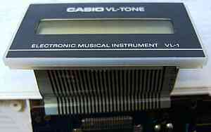
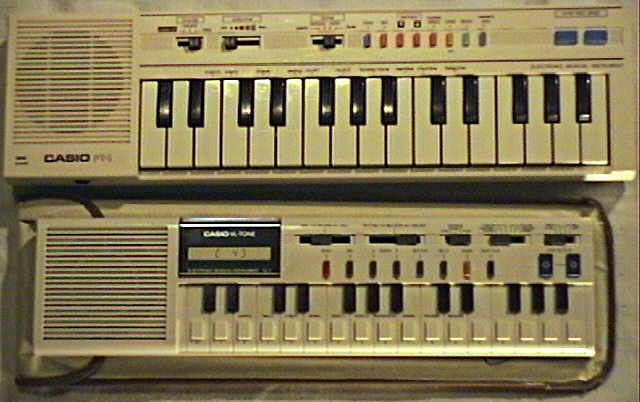
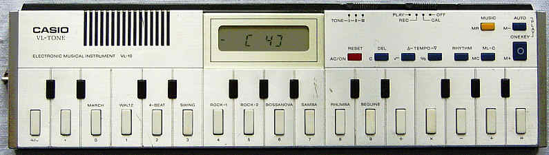
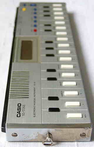
 Here you see the Casio PT-1 and below it my original VL-Tone
1 from 1981.
Here you see the Casio PT-1 and below it my original VL-Tone
1 from 1981. |
|
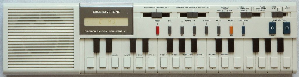
The VL-1 was also released as Realistic Concertmate-200 and a wine red French version as Liwaco LW-610. A really bizarre Russian clone (not using Casio parts, white or black case) came out in 1994 as Electronica IM-46 and Elecim 46.
|
Here you see the Casio PT-1 and below it my original VL-Tone
1 from 1981. |
 |
 |
 |
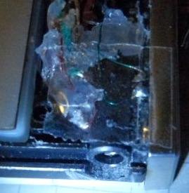
caution: Long times ago I forgot my Casio VL-1 in a wardrobe for about a year with batteries inserted. Likely from that time on the LCD became faint (black turned pale brownish) and never recovered. I am not sure if corrosive vapours from the slightly leaking batteries damaged it somehow, or if inserted batteries always (or only by a crash when empty?) drive a small DC current through the LCD, which deteriorates the liquid crystals over time. Thus always take the batteries out of the VL-1 before storage to prevent LCD damage. Also other Casio products (I bought a used Melody-80 calculator) seem to suffer of display ageing when running on batteries for years.
The sounds of the VL-Tone 1 have a somewhat grainy but pleasant timbre. They are all based on filtered multipulse squarewaves with different pulse patterns. But unlike my expectation the hardware does not switch filters among waveforms. The distorted vibrato (a zipper noise phenomenon?) turns a little slower during release phase of notes and its timbre resembles a bit an old Hammond organ's vibrato or Leslie. Particularly the 'fantasy' sound (a sort of creaky flute with distorted vibrato and reverb) is very typical for this monophonic instrument. (On Casio PT-30 this sound is a little harsher and less pleasant.) The 'violin' sound is astonishingly realistic (much better than with many sample based cheap keyboards) and also the 'flute' is ok. The 'piano' is a rather unnatural squarewave thing and the 'guitar' is a bad joke because (despite acceptable timbre) its linear envelope stops way too soon which sounds not remotely realistic.
The synthesizer can select between 7 different basic waveforms and has an ADSR envelope. The synthesizer also includes 3 timbres (selectable as basic waveforms) those rapidly toggle between 2 octaves as a sort of arpeggio; the toggle speed depends on actual rhythm tempo and thus is synchronized with the rhythm. Parameters can also control the vibrato and tremolo speed, but not their depth. Strange is that the vibrato depth seems to vary irregularly depending on the note pitch. The parameter resolution is each 10 steps because it uses for them the individual digits of the calculator "M+" memory. Vibrato and tremolo use independent LFO, those speeds do not match at the same parameter value, which causes an interesting beating effect. By a strange glitch vibrato and tremolo speed strongly increases (e.g. in 'fantasy' from 6 to 8 Hz) while additional keys or buttons are held down. Typical for this instrument and many other old Casios is also that even the fastest selectable attack rate is quite slow, which makes it impossible to simulate credible sounding picked strings (e.g. a guitar or harpsichord stays is always barely recognizable as such). In opposite to this the release phase can be set fast enough to make notes end with an audible click. The octave and sound select switches are only polled by the CPU with about 4 Hz, thus there is usually a noticeable audible delay before the sound follows the switch setting.
The rhythms are very recognizable because they consist of only 3 sounds (named by Casio 'Po', 'Pi' and 'Sha'), those are basically low & high clave (squarewave blips resembling the "Popcorn" synth sound) and a sort of (brushed?) snare made from shift register noise. If you like these minimalistic rhythms, also search for a Bontempi ES 3200 or variants; its rhythms sound very similar but have different patterns.
The sequencer can be edited and the note length can be changed afterward
using the "one key play" buttons. A beep during deleting a note indicates
by its duration the remaining memory space. (With only few notes entered
the beep is quite long, which can be annoying because it slows down the
deletion of many notes.) Playback tempo, rhythm and main voice sound can
be selected during playback and its sequence can optionally repeat 4 times
in a loop.
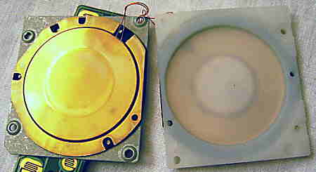
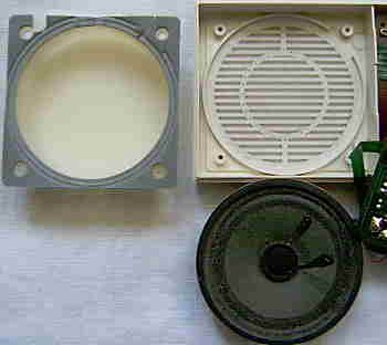 Especially
great on the VL-1 is that it contains a strange, cylindrical resonance
can of plastic behind its speaker, which permits to bend the sound in strange
ways by simply moving the left hand on the speaker grill during play (similarly
like jazz trombone players do with their instrument's funnel). Especially
well works this with the VL-1's famous and very sonorous "english horn"
sound (which is rather a kind of very low and creaky squarewave). The resulting
timbre is a sort of digeridoo- like and very precisely controllable. (Interesting
is that this play technique was originally already suggested in 1960th
in the manual of the first Stylophone.) Especially
great on the VL-1 is that it contains a strange, cylindrical resonance
can of plastic behind its speaker, which permits to bend the sound in strange
ways by simply moving the left hand on the speaker grill during play (similarly
like jazz trombone players do with their instrument's funnel). Especially
well works this with the VL-1's famous and very sonorous "english horn"
sound (which is rather a kind of very low and creaky squarewave). The resulting
timbre is a sort of digeridoo- like and very precisely controllable. (Interesting
is that this play technique was originally already suggested in 1960th
in the manual of the first Stylophone.)
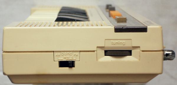
Other strange sound effects can be produced by placing the VL-1 next to a radio and switching the radio to AM or SW. The resulting sound in the radio depends on its tuning setting. |
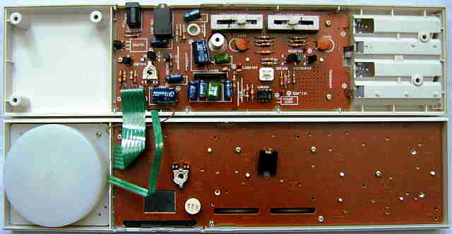
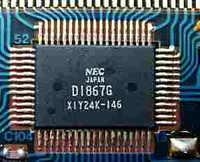
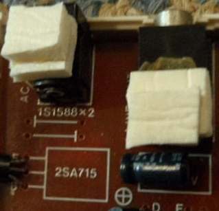
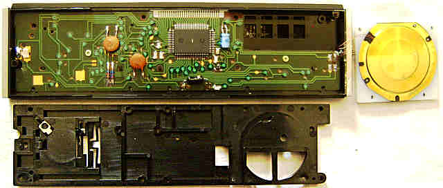
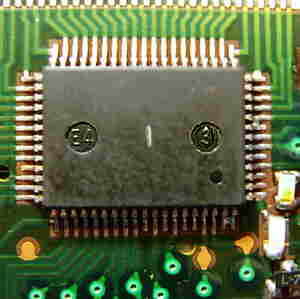
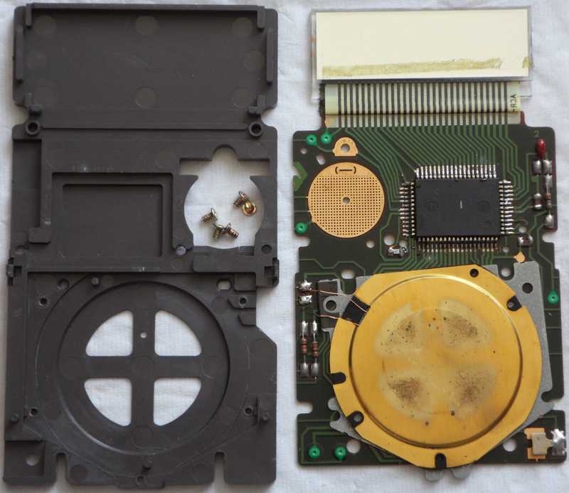
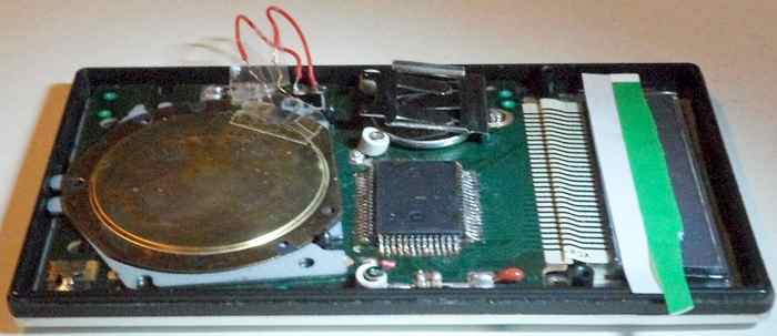
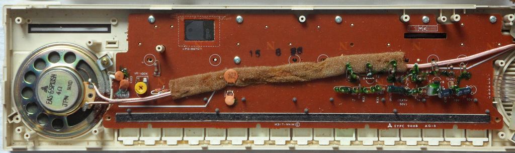
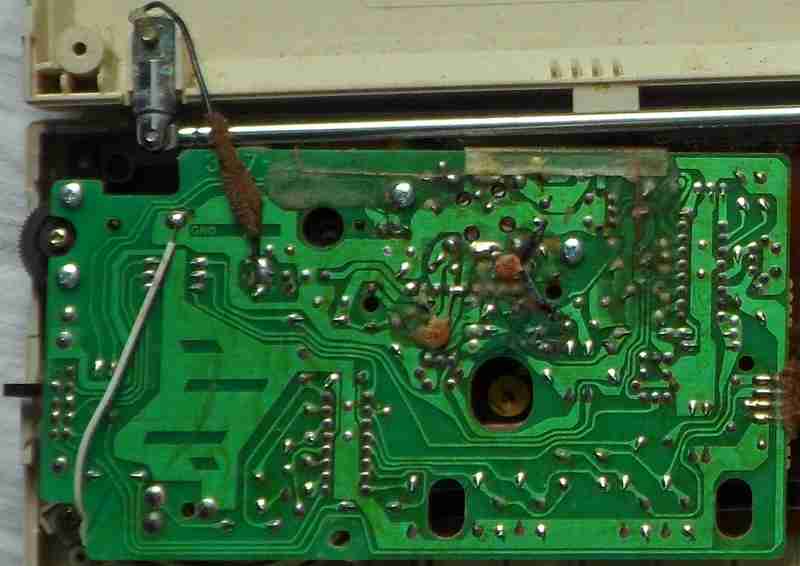
circuit bending detailsThe Casio VL-1 is based on the CPU "NEC D1867G" with power amp IC LA4142 (9 pin SIL).An indication of its pocket calculator origin is that (unlike later
small Casio keyboards) the CPU runs on only 3V. The instrument concept
(with sound generator hardware) is detailedly described in the US patent
4475429. The rhythm generator (with tempo +/- button and keys control)
is in US patent 4478123 and the sequencer in US patent 4448104. The instrument
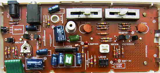
seems to be controlled more by gate logics than software. Unusual is the
main voice filter circuit that in 3 transistors extracts the digital envelope,
overdrives the waveform in op-amp (LA6368) back to squarewave, smoothens
the envelope output through a capacitor and re-mixes both in a primitive
VCA to iron out most of the zipper noise from the low resolution DAC. These
are the strange little patents those make Casio sound so special. (But
I guess similar filtering exists in basic guitar distortion pedals.)
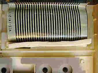
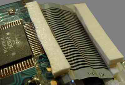
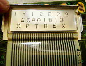
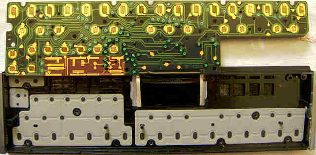
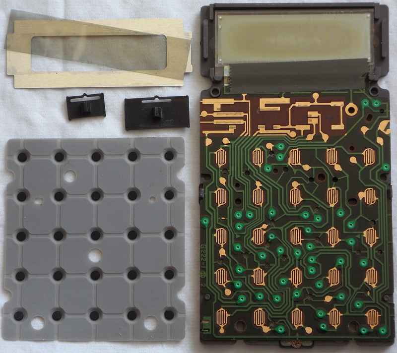
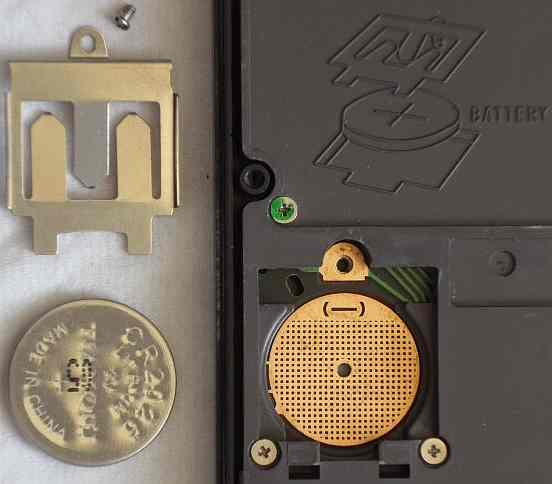
Robin Whittle wrote in his technical bulletin "Modifying the Casiotone Instruments" from 1981: "According to Mr. Noriaki Shimura, the president [later corrected he wasn't] of the Casio Computer Corporation, the VLSI chip that is the heart of the VL-TONE is equivalent in complexity to a 64k RAM and is the most complex chip ever developed for a consumer product. This means that it must contain about 70,000 transistors - nine times more than a Z-80 processor. The 64 pin chip senses switches using 8 drive and 9 sense lines like the chips in other instruments. Twenty of these switch positions are unused, one is permanently closed by a diode (without it the audio amplifier is not turned on) and the remaining 51 are connected to pushbuttons and slide switches. The main chip drives the liquid crystal display underneath which it is mounted, controls the power to itself and the audio amplifier, and has two analog outputs for rhythm and melody. If the VL-TONE is not used for three minutes or so the internal programs commit hara-kiri by turning of the the computer they are running in - as a friend put it: 'For the honour of the battery life I will turn myself off!' A capacitor maintains the melody memory while the batteries are changed, but no amount of discharging or interference will erase the indelibly programmed 'German Folk Song'. All the wave forms are square waves of different patterns - volume is varied by changing the top voltage of the wave."caution: The glued LCD foil cable is prone to tear loose; particularly at the panel glass its special conductive glue is brittle and can not be reattached with household means. (See LCD repair in the FAQ.) Thus if you take out the digital PCB, secure the delicate cable to the display frame with weak adhesive film to prevent pull against the direction of its glue seam. If the foil cable has partially loosened (some LCD segments disappear), attach a self-adhesive (window insulation) foam rubber strip under it to keep it pressed into place by the PCB during operation. If it fell off completely, additionally align it with a strip of adhesive film. But because all these methods are less reliable than the original glue, best avoid any (particularly skew) pull at the seam and handle it as carefully as possible.
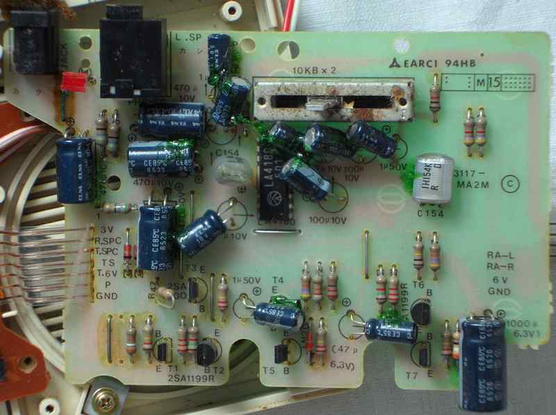
My original VL-1 specimen had survived lots of abuse I did as a kid to it and the later battery leak vapours those made the display fade. But finally the 'MC' button had stopped working; despite holding it down blocked any other pressed keys (thus the contact is ok and key matrix is still sensing its presence) it did neither delete the calculator/ ADSR memory nor the sequencer contents anymore. So I suspected a CPU defect by ageing and all that abuse. Years later I discovered that the rightmost black key was stuck down and could not be pulled out. After dismantling and sorting black keys correctly (which worsened foil cable trouble and made it fall off at the PCB side, which I fixed with foam adhesive tape) the 'MC' button magically worked again! Apparently eons ago I had wrongly put parts back together, resulting in key matrix trouble. Later I had bought a 2nd VL-1 specimen with different analogue PCB "GOMK-19EHB" uses the op-amp LA6355 as envelope follower. The preset sound switch failed by dirt because(?) a moron apparently had oiled it, so I had to dismantle everything for cleaning. I used this specimen for my CPU analysis. The foil cable from the main PCB (top to bottom) has the pinout {GND, +3V, APO, melody out, rhythm out, GND}. Burdening CPU pins with too much current reduces the clock frequency, causing the sound to howl. multipulse squarewaveThe monophonic main voice is based on multipulse squarewave sound synthesis. The digital oscillator outputs for each timbre an up to 16 steps long repeating bit loop of square blocks of equal height. (Because the internal rotation is unknown, I sorted them by the longest sequence of '1' as the start). Each preset sound also has a preset octave shift. The volume envelope height is 4 bit (15 steps, smoothened by analogue envelope follower). Surprising is that unlike other Casios the VL-1 does not contain switchable fix timbre filters. The sounds here are sorted by their synth timbre number. Sounds 7..9 toggle between 2 waveforms in the speed of tempo (not synced with note-on). The employed waveforms differ in the octave switch 'low' setting from the 2 other settings. The exact behaviour of these is hard to see on an analogue oscilloscope and so may be buggy. E.g. it may be that also sound 7 toggles only 2 octaves of the 'piano' (ratio 5:11) multipulse.
The 16 step multipulse squarewave sound engine without switchable filters is surprisingly effective. Later Casio keyboards those did re-introduce such timbre filters often suffer of too dull and quiet or thin high notes (like the horrible faint harpsichord of PT-50). Even the more complex waveforms (stairwaves) in their early polyphonic keyboards often could not compensate this; thus many timbres of VL-1 are actually superior to those preset sounds on bigger Casios of that era. Only the linear envelope with slow attack often prevents the VL-1 from sounding more natural. (Later Chinese keyboards like Hing Hon EK-001 routed this waveform generator through realistic analogue envelopes - with awesome results. Unfortunately nobody pushed things to the limit by making a real VL-1 successor that combines ADSR with polyphony and editable multipulses.) One reason for multipulse squarewave was certainly to simplify IC architecture with digital envelope. Due to steps can be only '1' or '0', it only needs to switch the envelope generator output on or off instead of scaling the waveform height. So it does not need multiplication hardware and hence less chip space. The choice of 16 steps may have been taken because the CPU is 4 bit and so can encode it in 4 words of each 4 bits and permits enough timbre variations. In general 16 bit equals 65536 combinations. Because their 16 rotations will sound identical, divided by 16 we still have 4096 combinations. Assuming that also backward played and inverted waveforms sound the same (only valid if no audible asymmetric distortion occurs and the multipulse is short enough), we again divide by 4 and have 1024 combination. Subtract 1 for the mute all-zero pattern, theoretically there can be 1023 unique timbres to select from (of those the VL-1 uses only 7). Simultaneous with the normal waveforms in VL-1 there are plain squarewave (ratio 1:1) versions available on unused CPU pin 20 and 21 (used by the piezo speaker of VL-10 and VL-80). These are certainly useful for circuit-bending to enrich the sound palette. As a current source their envelope is only present when burdened by a pulldown resistor (about 1k against 0V). The blip percussion consists of 2 plain squarewave blips with linear
envelope and a snare-like sound made from shift-register feedback noise
with 2 linear envelope sections (upper halve fast, rest slower). Also these
envelopes are 4 bit (15 steps) but not smoothed externally. Interesting
is that the percussion generator is indeed monophonic, i.e. with fast rhythms
the short sounds even truncate each other. According to the VL-1 service
manual, these percussion sounds are officially named Po, Pi and Sha.
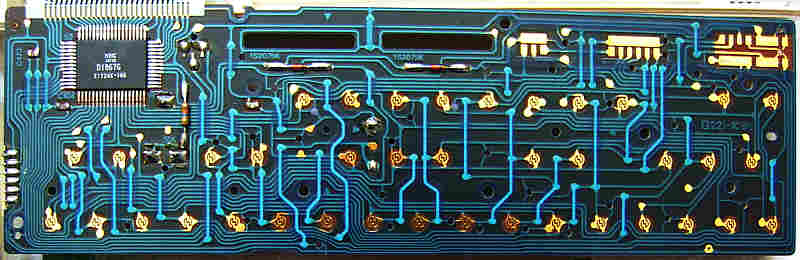
Additionally the CPU has unused trigger outs for external percussion. keyboard matrixA fundamental technical difference between the VL-1 and normal musical calculators is that the VL-1 matrix can properly recognize a 2nd pressed key (stopping the old note and starting the new one), which strongly improves playability. Other musical calculators (Casio and Sharp) start a note when the 1st key is depressed and then simply ignore everything else (i.e. holding multiple keys keeps the first note sounding) until all keys are released, which prevents fast play and particularly the intuitive use of multiple fingers. This makes the big difference between Casio VL-10 (based on VL-1) and e.g. Sharp EL-670, which despite similar keys feels way less responsive.By a strange glitch vibrato and tremolo speeds noticeably increase (e.g. in 'fantasy' from 6 to 8 Hz) while additional keys or buttons are held down, which makes me conclude that their LFO frequencies are derived from the same software loop that polls the matrix. Otherwise the tempo oscillator for rhythm and sequencer is unaffected and likely implemented in hardware, since it sounds very stable. This keyboard matrix was analyzed by myself, initially based on an incomplete
version found in the Casio PT-10 service manual. The layout is a
bizarre mess sorting sharps as own columns; the reason for this turned
out later, that is to say, the same CPU is also used in VL-80 which had
a much more calculator based user interface with a shift key for sharps.
The input lines are active-high, i.e. react on +Vs. Any functions can be triggered by a non- locking switch in series to a diode from one "out" to one "in" pin. The VL-1 matrix contains only 2 diodes; one at KO9 goes to the octave switch. The other is a fixed diode at KO9->KI4 that enables the CPU sound output. (In PT-10 schematics instead of the octave switch a fixed diode at KO9->KI7 permanently selects the mid octave, so you may desolder it and install a switch.) In VL-10 on the preset sound switch Tone I = KO7->KI8 (piano), Tone II = KO7->KI7 (fantasy), Tone III = KO7->KI5 (flute). The octave is wired "hi" by a fixed diode at KO9->KI8. The matrix out KO7 is polled slower and KO8, KO9 even much slower than
the rest, causing the instrument to recognize slide switch changes delayed.
Possibly this was done to save CPU time to speed up note recognition, or
even to reduce battery waste when idle (because one contact per slide switch
is always closed and so leaks some current). The sound select switch automatically
defaults to 'piano' with all contacts open, despite it has a dedicated
'piano' contact wired to a matrix place.
The octave switch works only in the regular VL-1 mode (diode at KO9->KI4); other settings have a fixed octave and the closed switch even interferes with key assignment (lowest note doublet on highest key). Also "one key play 2" (KO1->KI3) works in no other mode.
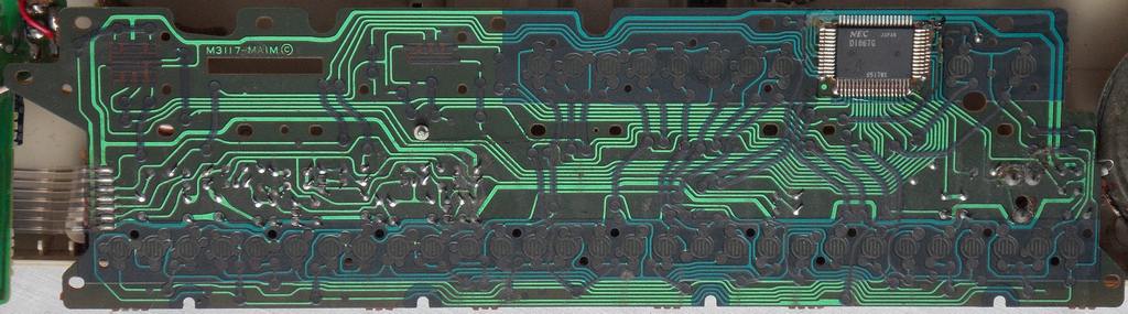
To do a manual cold reset (clear memory) in case of crash or lockup, also install the 'P' button from pin 59 (reset) to pin 58 (+3V). Like done in VL-1, you may bridge it with a small capacitor (47nF) to lengthen the pulse and make it less sensitive to interferences. In VL-1 an additional 100nF capacitor is wired from pin 2 to the pins 56+57 (those here are grounded to 0V). pinout D1867G, D936CTThe VLSI "NEC D1867Gxx" (64 pin SMD, pins count anticlockwise, xx = software number of internal ROM?) is the CPU of the Casio VL-1 mini-synthesizer and related mini keyboards. It outputs on 2 pins the monophonic main voice (made from multipulse squarewave with 4 bit linear ADSR envelope) and the rhythm made from 3 blip percussion noises {Po, Pi, Sha}, each containing coarse 4 bit envelopes. An external analogue circuit extracts, smoothens and re-mixes the main voice envelope into the waveform to reduce zipper noise. The most unique feature is the integrated calculator, which uses its "M+" memory to hold 8 synthesizer parameters (each a cipher); its 8 digit LCD is also used to display note numbers of the simple sequencer (100 notes in internal SRAM) and the tempo setting. According to Casio patents, the VLSI consists mainly of hardwired gate logics with very little program control, and thus is no CPU in the stricter meaning. Its close relationship to pocket calculators is also indicated by the fact that it is the only Casio keyboard CPU running on only 3V (used by the button cell operated Casio VL-10) and that the clock oscillator needs no external parts beside a resistor and trimmer. My VL-1 CPU has no software number (i.e. 1st revision?), but the PT-10 service manual refers it "D1867G11".The VLSI "NEC D936CT" (28 pin DIL) is a cheapened later versions without LCD support, that was used in some Casio EP-10 (possibly also PT-10) and Realistic Concertmate 350 (PCB version "M3215-MBIM"). I only read about it in a forum, but Traktor later identified the pinout, which lacks LCD pins but the rest behaves the same. This D1867G pinout is based on the service manual of Casio PT-10 (from April 1987), which unfortunately lacks many features. E.g. the pin names 33 to 51 (LCD port) were missing, so I concluded them from the given ones. I is unknown whether at all these should use alternatingly small and capital letters, or if they were just Japanese typos in the schematics. Because pins 20..23 already use capital 'B', I consider small letters more logical. I concluded the rest from VL-1 PCB photos and measured the rest. Important: Because in VL-10 and VL-80 this CPU is soldered upside-down
to the PCB, count their pins clockwise from lower right. The PT-10 service
manual indicates that this CPU uses "negative logic", i.e. technically
+3V is its GND while 0V is its -3V supply voltage. So the voltages are
not was the pin names suggest. I use the positive voltage naming convention
(from 0V to +3V, not -3V to 0V). To avoid damage, be careful not to feed
higher voltages than 3V from other PCB areas into the CPU.
The power switch in VL-1 connects CPU pin 58 (+3V) with pin 2 (/MI) when on or with pin 56 (ground) when off. So it apparently shorts the (high resistance) CPU supply voltage to choke it into standby mode (pulling ground up?). I haven't fully investigated this, but it needs no locking switch to stay on or off. The 'P'-button (which is bridged by a 47nF capacitor) connects the reset pin 59 with +3V to do a cold start (clear memory). A warm start (wake up from APO) is triggered by connecting KO6->KI8 ('reset' button) in the keyboard matrix. In PT-10 service manual "VDD" (pin 56) is ground 0V and "GND" (pin 58) is 3V from a voltage regulator transistor that is turned on by the "SPC" (pin 62) line. Auto-power-off will this way turn off the "GND" voltage. quote: "The voltage VDD (+3V) is always supplied to the CPU as long as AC adaptor is connected or batteries are set.The voltage +6V is supplied to the analog circuits and the power Amp. At APO (Auto Power Off) or when power switch is turned off, the terminal SPC of the CPU falls to LOW level. The transistors T4 and T5 turn off to shut the voltage +6V off." In VL-1 there is a capacitor (100nF) from pin 2 (M1) to pins 56+57 (both grounded to 0V). In PT-10 (service manual) the capacitor (47nF) is between pin 2 and pin 59 (reset), which erases sequencer memory during power on; in PT-10 pin 57 is not used. The clock rate is controlled by a resistor between pin 24 and 25. While VL-1 has a tuning trimmer, simpler models have a 150k resistor (147.9k in my VL-10, 152.7k in my VL-80) that makes pitch inaccurate. When messing with test modes, the VL-10 clock oscillator tends to crash into half(?) speed (LCD blank, sounds too low and slow). Unlike the R2D2 glitch of other musical calculators, it does not even return to normal speed by reset ("P" button), but only after battery removal. Pin 57 seems to be a test pin. Disconnecting its trace from 0V in VL-1 does nothing (still stays lo), but pulling it hi causes strange crashes and lights different display segments (e.g. "E"). It is hard to estimate what is going on there; possibly it just simultaneously connects logic circuits to an internal bus those should be mutually exclusive and so outputs nonsense. I e.g. once saw a rapidly running counter (like 1/10 seconds of a stopwatch) on the LCD and sometimes it seems to mix up play and calculator modes. With nothing connected, this also made the CPU think that the KO9->KI4 diode was removed, so it turned VL-1 sound off until next reset (press "P" button). After soldering a short test wire to it, often audio stays on when pulled hi, so the increased capacitance prevents some of this mess. In VL-10 I examined pin 57 closer. While pulled lo, there is plenty of data output on keyboard matrix KO pins (only KO5=lo, KO8 may be sync pulses). The height of the additional pulses apparently changes with voltage at pin 57 (which may help to distinguished them from normal matrix pulses). Pulling lo during reset displays a dot. Pressing keys does LCD segment and semi-random sound mess. Particularly {"+", "-", "×", "÷"} change data (internal addresses?) and the "rhythm" button seems to somehow advance through segments and modes. Sometimes it starts the demo (in non-VL-1 modes) or plays individual strange sounds (rarely also percussion noise variants). Pulling keyboard matrix ins hi during reset triggers various test functions. Pulling KI2 hi shows LCD test pattern "0000#0000#" with power on, or a row of dots and all math symbols when off. Test pin 57 pulls here some KI pins hi. Pulling KO1 hi turns LCD and CPU off; after power on it shows the test pattern. The LCD display signals are made from 4 voltage steps {0V, 1V, 2V, 3V}; unlike the archaic VL-5 hardware it needs no external resistors to generate them. The CPU has an alternative set of unused audio outputs, those were designed for piezo speakers and also stay active without KO9->KI4 diode. The alternative melody audio out pin 20 produces always plain squarewave instead of the multipulse waveforms. Its volume envelope only takes effect when a pulldown resistor (about 1k) is attached. Pin 21 does the same like 20 with the squarewave inverted. In VL-10 and VL-80 these are wired directly (though resistors) to a piezo speaker that gets both waveform halves to do its best of the limited voltage range. Pin 22 outputs the percussion tone of Po and Pi (without envelope?). Pin 23 is like 22 but turns hi during Sha. Both remain unused in all models. (The VL-10 percussion uses the normal pin 64 through a transistor to a separate piezo speaker with parallel inductor for resonance.) The unused pin 60 turns hi during Po and pin 61 during Pi, which were likely intended as triggers for external analogue percussion but are not used in any model. In VL-10 and VL-80 is a short trace at pin 61 that goes nowhere. Traktor told me, in D936CT of his Realistic Concertmate 350 the unused pin 28 is lo (nothing comes out) and turns the unit off when pulled high (against +3V). Pin 27 is completely NC (high resistance, may be internally not connected). The correct order (in, out) of clock pins 15 and 16 is unknown and may be wrong. Keyboard matrix eastereggs and reset mod work correctly like in VL-1, thus the chip die is likely identical. The soviet VL-1 clone Electronica IM-46 is based on the CPU "CM1-2" (64 pin SMD), which square package has a different pinout (seen in datasheet). |
|||||||||||||||||||||||||||||||||||||||||||||||||||||||||||||||||||||||||||||||||||||||||||||||||||||||||||||||||||||||||||||||||||||||||||||||||||||||||||||||||||||||||||||||||||||||||||||||||||||||||||||||||||||||||||||||||||||||||||||||||||||||||||||||||||||||||||||||||||||||||||||||||||||||||||||||||||||||||||||||||||||||||||||||||||||||||||||||||||||||||||||||||||||||||||||||||||||||||||||||||||||||||||||||||||||||||||||||||||||||||||||||||||||||||||||||||||||||||||||||||||||||||||||||||||||||||||||||||||||||||||||||||||||||||||||||||||||||||
Interesting is that the so-called "German folk song" was not only the demo tune of the VL-Tone 1, but was also used in various Casio pocket calculators (e.g. my ML-90, on which calculator keys one can play piano in piezo sound). Later a wonderful orchestrated version of this theme appeared as one of 4 songs (labelled "Unterlanders Heimweh") on the music cartridge "ROM-Pack RO-551", which was shipped as the default cart with many cheap ROM-Pack keyboards. A badly detuned short clip of the melody was even used in the "rating" sound effects of the Casio PT-82 "melody guide" play teaching feature, and later the melody appeared as one of many songs in various "song bank" keyboards. Thus it can be likely considered a kind of unofficial Casio anthem. To me it was one of my childhood key experiences with electronic music.
But here in Germany it is definitely not a commonly known standard folk song. Most bizarre is that apparently nobody else than Casio ever referred this as "Unterlanders Heimweh", so it is likely wrong despite the ROM-Pack RO-551 lists this name.
Blatantly based on this version was the title theme and background music of the Atari VCS2600 lightgun game prototype "Shooting Arcade" (©1989 Axlon / Atari). I own a Casio MT-36, which demo tune "Unterlanders Heimweh" (name in manual) is a rural folk waltz piece that is very different from the VL-1 melody. I also bought an Elite MC2200 keyboard that has many demo tunes of those one is labelled "UMTERLANDERS AEIMWEH" (regard the typo), and the Letron MC-38 that includes it too (misspelled "UMTERLANDERS HEIMWEH); both melodies corresponds to the MT-36 and not the famous demo of VL-1. The MT-36 melody is definitely the genuine documented "Unterländers Heimweh" (means something like "Lowlander's Homesickness", regard the 'ä'), alternatively known as "Drunten im Unterland" (means "Down in the Lowlands", ©1835 by Gottfried Weigle, seen on YouTube with German lyrics).
When I bought and repaired a Citizen - Melody Alarm clock with 8 polyphonic tunes, it turned out that it included the VL-1 melody, which in its blurred manual (only an eBay photo) was listed as "Musician of the Mountain", which appeared to be a translated title of the Japanese children song "Yama No Ongakuka" (Mountain Musicians). After hours of websearch in different languages I thought that the original German title of this folk song was "Ich bin ein Musikante". This is a traditional (lesser known) children's game song about a musician, involving vocal imitation and miming of the many instruments he plays (a well fit choice for the first mass produced toy-size mini synth). But the melody in all YouTube examples clearly differs, hence there was no exact German equivalent known, and also in YouTube "Unterlanders Heimweh" examples with RO-551 melody I found no other concrete hints of origin than Casio and particularly nothing with German lyrics. Another similar song is "I Am a Fine Musician", which has yet another different melody.
So it has to be be concluded that the only "original" of the VL-1 melody is the Japanese children song "Yama No Ongakuka" (about forest animals playing different instruments on a mountain), which concept was only inspired by a German folk song ("Ich bin ein Musikante") and on the ROM-Pack accidentally was misnamed by Casio as "Unterlanders Heimweh" (without 'ä' umlaut) until it got known worldwide under this wrong name. Generally Casio in their early products (e.g. barcode song books) applied the term "folk song" or "traditional" quite sloppily - possibly as an excuse when they didn't know the author or even to avoid paying royalties. Thus the "German folk song" indication had to be taken in doubt.
The story could have endet here. But finally a youtuber (who did not credit me either for my previous investigative work) identified that this song had indeed German origins. That is to say, in a German children's song book "Kinder-Gärtlein" of 1841 there was a German folk song "Das Lied vom Musikanten" (The Song of the Musician) which had an almost identical melody, but with additional middle part and a few different finishing notes, and also had lyrics about vocal imitation of musical instruments. The Japanese version "Yama No Ongakuka" appeared first in april 1964 in the children's tv show "Minna No Uta" ("Everybody's Songs" by NHK, featuring translated children- & folk songs), played by the band Dark Ducks and arranged by Katsuhisa Hattori with lyrics by Takatomo Kurosawa (claimed translation based on "Ich bin ein Musikante"), so apparently something got mixed up.
On Casio Music Forum a person OBattler found out that "Das Lied vom Musikanten" appeared in an even earlier German songbook in 1838, but in a book of 1890 they published under that name a different song identical with the modern "Ich bin ein Musikante". He found a recording by the Waldsteiner Sängerbund singing a version "Ich bin ein Musikant" with the melody middle part and there are several others, which hints that the melody gradually mutated over time. Apparently also a South Korean ("Saneui eumgagga") and a Chinese language version exist, with lyrics corresponding to "Yama No Ongakuka" and melody with or without the middle part from "Das Lied vom Musikanten" in a wrong place. In Japan the melody of "Ich bin ein Musikante" exists as "Minna ongakuka" (Everyone is a muisician). Also a Slovenian variant "Jaz sem muzikant" with yet another slightly different melody exists. The oldest similarity may be in the theme of Mozart's Allegro in F (KV. 1c) from Nannerl's Music Book (1759-64), which apparently was written by Wolfgang's father Leopold Mozard for his older sister Nanerl in 1761. But there are several German folk songs with similar melody lines, including "Vogelhochzeit", "Gestern Abend war Vetter Michel da" and "Der Kuckuck und der Esel", those thanks to the lack of copyright gradually mutated and mated across centuries by evolution at work. But the melody on Casio VL-1 most clearly corresponds to the Japanese "Yama No Ongakuka".
 |
 |
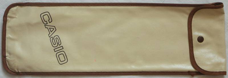
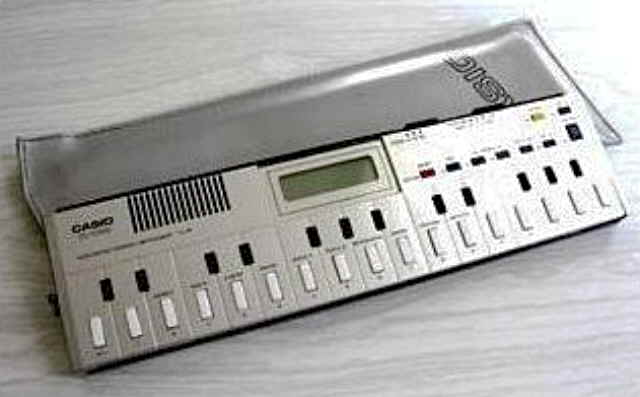 This is just an eBay photo; my VL-10 lacks the bag.
 |
 Also
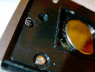
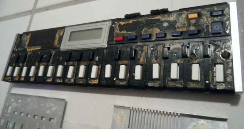
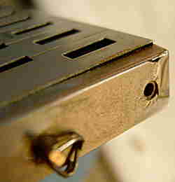
the metal plating is rotten... Also
the metal plating is rotten... |
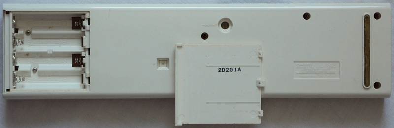
...and the battery cover is gone. |
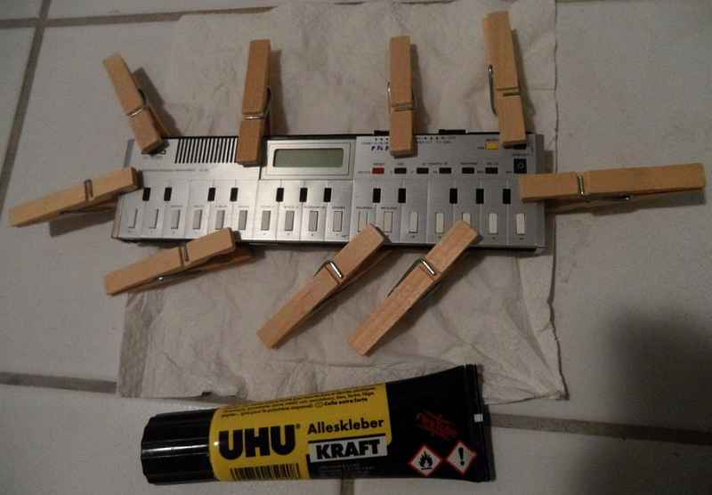
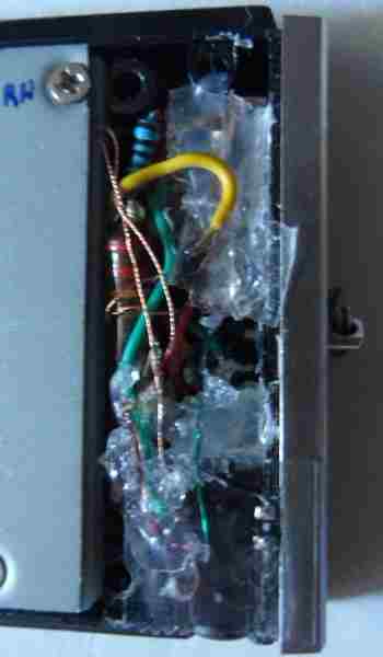
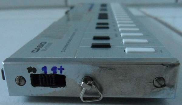
my upgraded controls |
 |
 |
everything of Casio VL-1 addable.
The VL-10 timbre differs from VL-1, because it uses the plain squarewave
output of the CPU that makes them duller. The preset sounds 'I', 'II',
'III' correspond to 'piano', 'fantasy' (1 octave lower) and 'flute'.
circuit bending detailsThe Casio VL-10 is built around the D1867G CPU like VL-1 (soldered upside-down, print unreadable), thus for general hardware description see there. Although some unused pins differ, it is wired basically the same and to my surprise even runs in the same mode. Only the main voice speaker is wired to the plain squarewave outputs and hence sounds different.
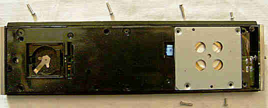
It is hard to understand why Casio didn't make it more VL-1-like. The battery backed-up sequencer, calculator mode and LCD is all there, so it is electronically easy to upgrade this thing with the ADSR synth. So as a proof of concept I eventually decided to add most VL-1 slide switch features; although on the case rims is enough space to mount tiny slide switches and an output jack, this is mechanically intricate and not recommended. The only absent thing is the analogue envelope smoothening circuit (which however permits more percussive attacks) and volume pots. After the upgrade, it undoubtedly constitutes one of the world smallest and least energy consuming self-contained synthesizers, and it is quite exciting to find out what happens when the different envelopes and timbres are squeezed out through its internal piezo yellcoin. Surprisingly it holds the memory contents for at least an hour with battery removed. important: The VL-10 tends to howl when its button cell gets weak. Particularly modern cheap CR2032 tend to age badly and even unused after few years develop high internal resistance despite their 3V voltage looks perfectly ok. So if sound worsens during experimentation, don't panic but try a brand new battery. For anything you upgrade, regard that the instrument runs on only a small button cell and has no physical power switch, so do not install anything that keeps consuming electricity when no sound is produced, else it will rapidly drain the battery. Dismantling this thing is a little tricky since it employs many different screw lengths and the 2 fairly big piezo speakers hang on thin enamelled wires. Like with other Casio VL-series keyboards, also here the loudspeaker assembly is a unique special construction that I never saw anywhere else. A small spring electrically connects the case bottom with the front panel to protect against static electricity (don't loose it). Although small, the case is high enough to fit some upgrades. Because the CPU is on the back (pins count clockwise from the lower right), it is even safer to examine than a normal VL-1, because the PCB does not need to be taken out to reach it, so the fragile LCD foil cable will not be stressed or lifted to get underneath.
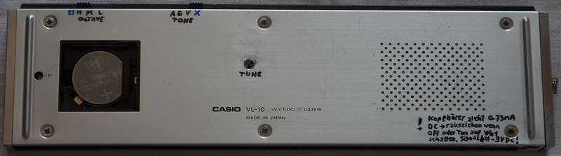
tuning trimmer The clock resistor (marked "154" = 150k) has 147.9k. Installing a 500k tuning trimmer or pot is recommended to set pitch properly. octave switch & ding mode The right diode (KO9->KI4) is necessary to enable the VL-1 sound mode (else there would be no rhythm and different sounds). The left diode (KO9->KI8) however is completely useless! That is to say, it simulates an octave switch in "hi" position, however the CPU resets to the hi octave anyway. Likely either the rom software or CPU specs was not finished when the PCB layout was made, or (less likely) it was meant to complicate reverse engineering. So I desoldered the upper end to wire a 3-octave switch to CPU pins 8..10 here. (You also need to disconnect it if you want to experiment with different CPU modes (right diode), else the highest key plays the lowest note.) So I used a 4 position 2 row slide switch, and kept the 4th position as an additional no-diodes mode (aka "ding mode") to enjoy a different sound set. To do this, remove the VL-1-mode diode (KO9->KI4) and instead wire the first 3 slide switch positions input to KO9 and from the 3 corresponding outputs each a diode to KI6, KI7, KI8 (the octave modes) and (this is the trick) each an additional diode to KI4 (mode select VL-1). This way the 3 octave settings keep VL-1 mode enabled, while switch position 4 will disconnect all diodes from KO9 and so switch into a mode with different squarewave preset sounds at pins 20, 21 (the VL-1 melody channel at pin 63 and rhythm stays mute), those need an additional preset sound switch to select. ADSR synth & more preset sounds In VL-10 the "tone" switch only selects Tone I = KO7->KI8 (piano), Tone II = KO7->KI7 (fantasy), Tone III = KO7->KI5 (flute). To get all 6 preset sounds + ADSR synth, cut the trace at the KO7 output pin 17 to the tone switch and wire it to a switch with more positions to select KI3..KI8. I used only a 4 position slide switch (which is smaller) with its common input wired through a diode to KO7, and the 4 outputs to KI3 (ADSR), KI4 (guitar), KI6 (violin) and (this is the trick) to the disconnected trace end to the tone switch (that originally was at pin 17). This way the new switch can select 3 new sounds and at its 4th position use the original tone switch to select its sounds like before. The ADSR synth will function like in VL-1 by storing a number in M+ calculator memory. The ding mode (no diodes at KO9) uses the 3 additional positions of the new switch for its preset sounds. In ding mode the VL-1 melody output is muted, thus only the squarewave output (pin 20, 21) works. Here 'violin' becomes a plain squarewave organ at high octave with percussive attack and about 2.5s long sustain (typical musical calculator/ greeting card tone). 'ADSR' becomes same with about 5Hz vibrato. 'guitar' becomes like 'violin' in 1 octave lower. All others see 'violin' (i.e. all 3 of the original tone switch sound the same). VL-1 multipulse sound amp Originally the melody voice piezo speaker is directly wired through 2x 100 Ohm resistors to the squarewave output pins 20, 21 of the CPU. The separate rhythm channel speaker is connected to pin 64 through a single-ended transistor amp and (like in Casio Melody-80) has a parallel inductor to play loud and harsher. So for a quick test I shorted CPU pins 63 & 64 to play the VL-1 multipulse voice through the rhythm speaker. The demo timbres (although a little harsh) were clearly recognizable, but this muffles rhythm too much and is not recommended due to overload risk of the output pin. But with proper capacitors and resistors the piezos definitely can do more than plain squarewave. (It should be made switchable to preserve the original timbre.) The rhythm audio from pin 64 is connected through a 33k resistor to the base of a NPN transistor. The emitter is ground 0V and collector outputs through a 330 ohm resistor to the (-) pin of the piezo speaker, which (+) pin hangs on +3V. Parallel to the speaker is an inductor, which inner resistance is important to make current flow at all through this single-ended amplifier, because piezos acts like a capacitor with infinite DC resistance. The amp is designed to draw no standby current while the CPU outputs no sound. So for the multipulse melody audio at pin 63 I cloned this amplifier. Instead of the original SMD transistor "L-7" (NPN, measured B=488, Uf=641mV) I used one from an old camcorder (B=213, Uf=705mV, same pinout) and an inductor (e.g. 27.6mH 194 ohm). Instead of the inductor also a 330 ohm resistor may be used, but will sound quieter. To make the sound output selectable, I had to mod a switch in a way that is not optimal, but it was hard to make it fit. I used a bridging 2-row 4-position switch that I mechanically modded into a 2.5 position switch (i.e. it slides only until bridging position 2 with 3) by soldering a wire inside of it. The common pins are connected to the piezo speaker. Electrically it is not optimal and my notes are a big mess, so I am not sure if I describe it correctly. row 1:
row 2:
This way in position 1 the melody speaker gets only the original squarewave from CPU pins 20, 21. In position 1+2 it mixes squarewave with output from the multipulse amp (while avoiding to short pin 21 with +3V). In position 2 there is no melody channel (only rhythm), which is necessary to prevent shorting pin 21 with +3V. In position 2+3 it connects the speaker with multipulse amp and with inductor to +3V at one end and with +3V at the other; so it plays multipulse loud and brighter. (The rhythm runs through its separate speaker.) It is important not to burden multipulse audio outputs of CPU or amplifier when not in use. (Remember, it runs on a button cell.) For the inductor I wired in series 2x 22mH, which sounded too harsh, so I added in series 270 ohm, which (due to the capacitive nature of piezos) made it dull enough. sound output For sound output I used a very slim SMD 3.5mm jack from an old mini camcorder, which unlike a standard stereo headphone jack had 4 instead of 3 concentric contacts (so one remained unused) and a switch contact to disable internal speaker. (I disconnected the +3V side to disable both?) To make the plug slide in deep enough, I had to cut out a piece of the protruding front rim of the case. I wired rhythm to the left (tip) channel (measures 238 ohm to +3V), melody to the right (2nd ring) channel and +3V to the GND (shaft) of the stereo plug. So on e.g. a 32 ohm stereo headphone or 150 ohm test speaker I get rhythm on the left and melody on the right side. (With stereo headphone I also get melody voice in channel switch position 2, likely because its inner resistance makes current flow through the rhythm channel.)
warning: Another flaw is that the melody output line at the jack will have a -3V offset (-1.5V during sound) and always draws 0.75mA standby (even with power off) through the load when shorted or 32 ohm headphone connected, which drains the button cell when not unplugged. Selecting only VL-1 melody at the channel switch (position 2+3) prevents this. The DC offset may even damage audio inputs of connected devices, thus make an audio adapter cable containing an external 1k(?) resistor against jack GND (actually -3V) and a 100nF capacitor to the audio input. (If I remeber well, I did not place the resistor inside the VL-10 to avoid standby current.) Generally this thing is still a bit messy and more a proof of concept to explore why Casio refused to make the VL-10 this way. Nevertheless it has a different sound palette than a regular VL-1 because the the squarewave and ding mode sound duller than standard VL-1 timbres, and the omitted envelope filter makes the sound snappier with more zippernoise overtones. |
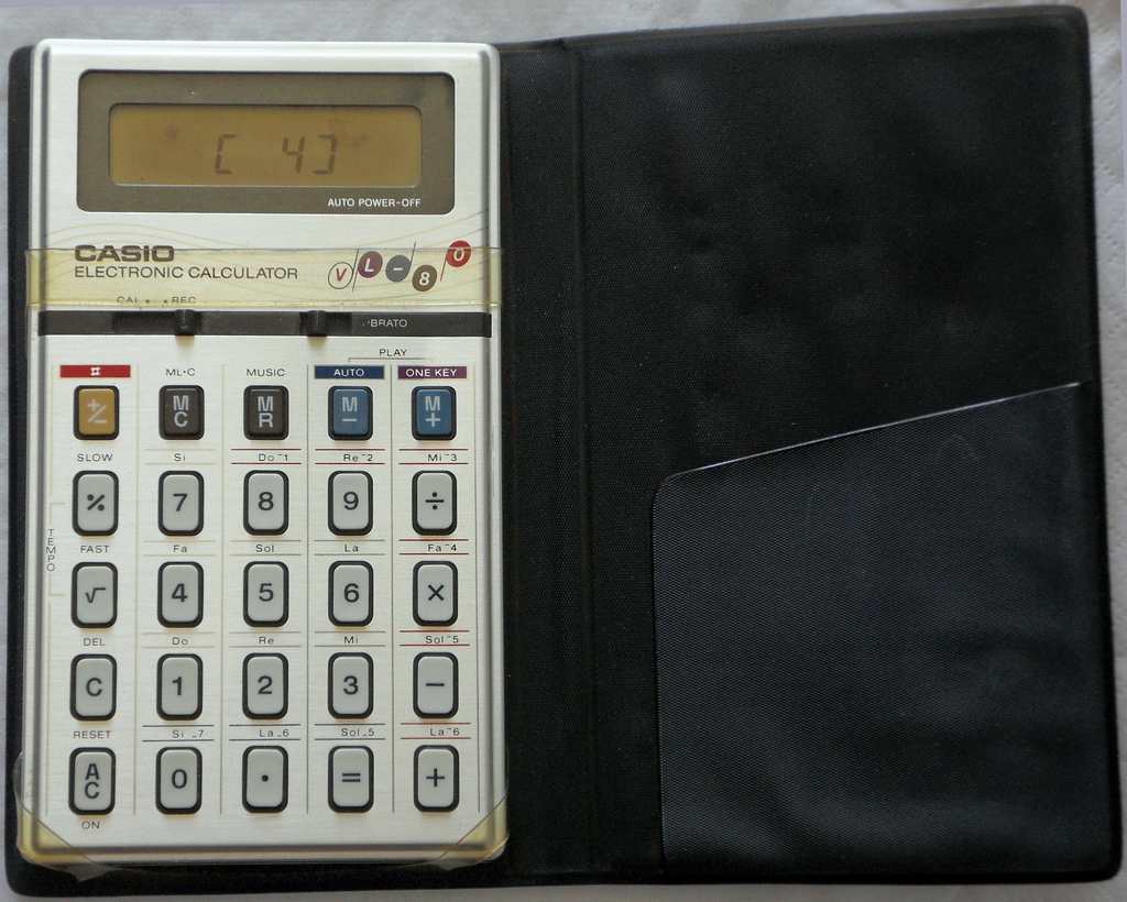
The behaviour has some similarities with the well known Casio VL-1, although it has neither rhythm nor synthesizer. The sound is only a plain squarewave organ tone with sustain (digital volume envelope), which was typical for musical calculators.
 |
 |
 |
ADSR synth mode on vibrato switch (wire bridge at KO9->KI3 instead of KO9->KI5). (theoretically all of VL-1, but barely useful due to different panel layout.)
Like VL-1, the VL-80 has separate music and calculator mode, hence it
can neither sound typed ciphers nor calculation results as musical notes,
and by improved key scanning algorithm the music mode permits faster play
than average musical calculators. The keyboard matrix can sense 2 key or
button presses exactly like VL-1 and increases LFO speed too. Despite very
different user interface (vibrato switch, some calculator functions on
different note keys, a button turns naturals into sharps) it has the same
CPU, which was an ordeal to find out because as the only model of its hardware
class it runs in a different operating mode.
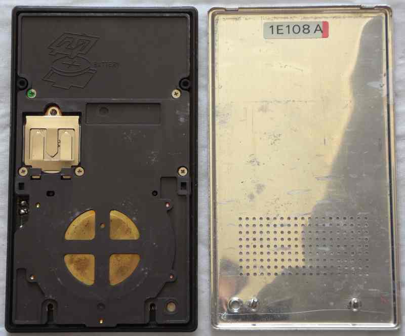
hardware detailsDespite very different user interface and sound, the Casio VL-80 is obviously based on the same "NEC D1867G" CPU like the regular VL-1. (The CPU label is invisible, but in tests I could find plenty of regular VL-1 modes as eastereggs.)
|
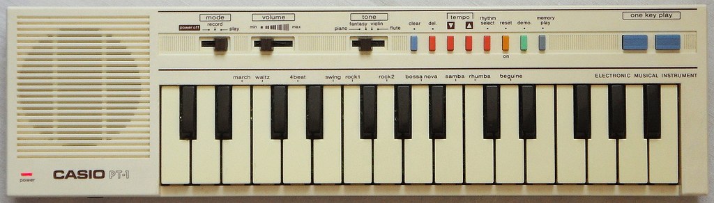
In 1984(?) Casio released the PT-1, which was based on the same CPU like VL-1, but had no LCD display, no transpose switch, no balance slider and no calculator mode and thus no synthesizer anymore (also the lousy guitar sound is gone, though only 4 sounds remain). This instrument was also released as Realistic Concertmate-300and a silver grey French version as Liwaco LW-600. The original German retail price of the PT-1 in a German Conrad catalogue from 1988 was 99DM (about 50€). It was also released as Realistic Concertmate-300.
 |
 |
 |
 |
 |
 |
 |
 |
 |
 |
 |
 |
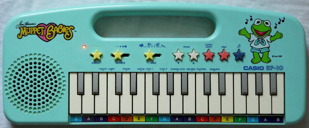
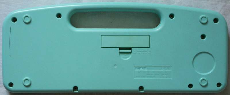
This light blue plastic bomber was technically like Casio PT-1, but is even missing the sequencer and tempo control, thus only 4 sounds, the rhythms and the demo tune remained - what a shameful end for such a great programmable synthesizer hardware. Interesting is that my EP-10 has the roughest and most impulsive sounding percussion of these instruments - possibly Casio omitted some filter capacitors to save cost.
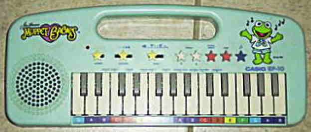 (old eBay photo of my specimen)
 |
 |
 |
 |
 |
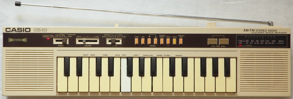
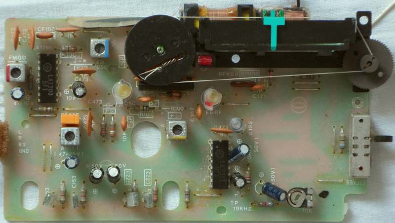
Other keyboards with the same CPU like the VL-1 were PT-10 & PT-12 (aka Realistic Concertmate-350, resembling PT-1), PT-22 (similar with 2 speakers) and CK-200 (ghettoblaster with radio and cassette deck). Unfortunately they all lack the synthesizer.
A 4 note polyphonic relative of Casio VL-1 was the Casio
VL-5, which featured a barcode reader to scan digital musical scores
from a book into the internal sequencer. The VL-5 is unfortunately pretty
rare now and has no synthesizer. In opposite to this, the original VL-1
is still rather easy to find on eBay, thus everybody who wants to try out
"the real thing" can still get this wonderful piece of electronic music
history. (The digeridoo trick works only well with a real VL-1 or VL-5.)
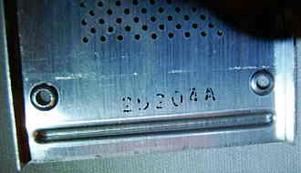
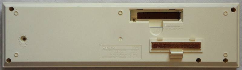
| removal of these screws voids warranty... | ||
 |
||
|
|