 |
version of 2025-12-10
|
|
version of 2025-12-10
|
[guide for safer circuit-bending]This FAQ is about the modification of cheap music keyboards and electronic sound toys to convert them into unusual music synthesizers.
Maintainer of this FAQ is CYBERYOGI =CO=Windler (e-mail: CO-WindlerSP@MWeltenschule.de - Replace "SP@M" with "@" to answer.) This FAQ comes with absolutely no warranties - particularly I can not guarantee that the technical explanations and safety tips in this FAQ are fully correct, complete and up to date, therefore whatever you may do by instructions and tips found in this FAQ, you will do it solely at your own risk. I also can and will not teach you in this FAQ the general basics of electronics or synthesizers; on the internet are plenty of other sites to explain these.
The newest version of this FAQ can always be found on the WarrantyVoid
site:
http://weltenschule.de/TableHooters/index.html
The simplest (but not always healthiest) form of circuit- bending is the naughty act of simply opening the case of a low voltage (battery operated) sound device and stick ones hands straightway into the circuitry to temporary short electric connections by fingers to play sounds on it. Though circuit- bending can be basically regarded as a cyberage's anarchic successor of phono record scratching, which also only got possible by systematically ignoring all grannies warning: "Don't touch the precious gramophone discs with your smeary, sweaty fingers!". ;-) The same way circuit- bending lives from systematically ignoring any "warranty void" warning stickers on its explorative mission to boldly hear what no man has heard before...
In more elaborated forms of circuit- bending additional potentiometers, buttons and other controls get soldered to the circuit of a sound device to modify it into a synthesizer- like musical instrument. I always thought I would be the only electronics hobbyist with the strange hobby of modifying sound toys, until I discovered the homepage of the artist Reed Ghazala (see here), who since long times does quite the same and created for this the term "circuit- bending". Already in my childhood I dismantled my Casio MG-880 melody/ game calculator, made its remains' melody pitch (clock speed) adjustable and played it at full volume through the record player input of my grandma's radio. I also placed my Casio VL-Tone 1 onto the radio and switched the latter to AM or SW, which makes tons of funny distorted synth sounds receivable in the radio (depending on the radio's tuned frequency). I also often wiggled the VL-Tone batteries at their contacts, which made often quite bizarre sounds, melodies and symbols appearing on the LCD.
Nowadays I modify instruments usually more planful than I did in my
childhood, and unlike Ghazala* (who encourages
people to ignore theory and simply play around with shorting connections
on the PCB by trial and error without caring much what they technically
do) I am e.g. particularly systematically searching for "eastereggs", i.e.
extra chip functions those were not wired to buttons because they were
intended for a more expensive version or test purpose etc. E.g. many old
keyboard instruments (with one button per rhythm) contain way more rhythms
than buttons are present on the control panel. But I also mess around with
the clock oscillator (including exploring effects of crashes by overclocking),
add potentiometers to the individual sound channels of an accompaniment
circuit, distort things and much more.
| *) Reed Ghazala calls his techniques "anti-theory", but sometimes a bit of scientific/ technical theory can help a lot, so far it doesn't transform people into herd- animalish cookbook engineers incapable to think by themselves. (I went successlessly at the Technical University of Hamburg- Harburg through 6 semesters of "technical computer science" (which is based on electrical engineering) before I started my software- techniques studies, though I learned plenty of "theory" (and white science's prejudices) there.) Look at Friedensreich Hundertwasser; he also needed some architecture theoretical basics to become capable to create buildings those don't collapse; in spite of this he didn't repeat the same boring and shape- aggressive rectangular concrete block rubbish that other architects do. Important is just to stay capable to think differently in spite of all that "theory" (to which my enlightenment enabled me). I may think like an engineer scientist, but I feel like an alchemist. |
My approach is much more systematic than what Ghazala tells the world, but not to understand me wrong - circuit bending needs no studies of electrical engineering and simple forms can be done by everyone - even a kid can find interesting sounding results by trial and error. But in spite of this, blindly shorting IC connections can be quite dangerous for electronics and result in expensive and annoying damages. I think that an instrument that you build by this method should last as long as any professionally manufactured one and not burn out after a few days or months for obvious or even totally unobvious reasons, and it also should not become a health risk. I therefore wrote down this FAQ for safer circuit- bending and tablehooter modifications...
If you need to solder simple SMD parts in absence of a suitable soldering station (e.g. on a travel), you can improvise a small size soldering tip by winding a piece of 1mm copper wire around the tip of a regular size soldering iron. But by the lack of temperature control this is mainly for emergency repair and not recommended as a permanent solution.
SMD part specs often request a strict soldering temperature. Although this is likely more relevant with devices like reflow ovens (those heat an entire PCB for minutes), too much heat can shorten component lifespan. If no exact value is known, with the iron of my soldering station 330°C temperature turned out to work well. Too low melts too slowly and so exposes components to longer heat stress. Too high can make PCB traces tear loose, releases more toxic fumes and oxidizes surfaces much worse. The main benefit of a soldering station (with heat sensor) is that the regulated small iron can have much higher wattage than needed to hold temperature (it would glow without control), so it will quickly reheat after draining heat to a workpiece, which is particularly useful with multi-layer PCBs or or large metal contacts.
But stay away from moonpriced boutique soldering irons (Weller, Ersa) with special fit exotic coated "longlife" tips. Much like so-called "name brand" jeans, these tips last perhaps 2 times as long for 10 times the price. IMO they are a scam product for planned obsolescence. As a kid I had an unregulated Ersa iron which "longlife" tip quickly developed cavity until its end broke off and had to be replaced several times; the initial specimen even came with broken heater and (like all irons finally do) also the heater of the exchanged iron somewhen burnt out. Some people claim that solder has to contain copper and that a temperature controlled iron (stay <400°C) makes such tips indeed last longer. But longlife tips are forbidden to touch anything abrasive (like steel sponge or sand paper, but in fact also the metal you solder!) and rapidly develop cavity (worse than others, by electro-corrosion by the coating metal?) once their surface got slightly scratched, forcing you to buy the next special patent fit tip again and again. IMO at least for non-SMD a proper soldering iron has a shaft with a screw at its side and a cylindrical hole where a generic copper tip is inserted. Once the end rots off, you unscrew the tip (to avoid tool vibration and raw force against the heater), file it back into shape and reuse it. It is just a thick copper bolt, thus if it got too deformed to be filed (mine got a hole at its end that squirted liquid solder everywhere) saw the end off diagonally and you have a pointed tip again. You may even turn it around to use the other end. And if it gets too short, simply pull it out of the shaft a little more (the screw is near the very end) to use it much longer. Of course pulling out too far will worsen thermal contact to the heater and so heat up a bit slower and possibly wear down the heater preliminary. But a proper iron (the kind from your local property store) can take that abuse long enough to save many times the cost you waste with boutique tips.
Some people also use a (plug-in) lamp dimmer with a cheap unregulated iron instead of a soldering station; although without sensor it won't heat up as quickly, it is the cheapest way to reduce temperature for delicate work. (Casio and many cheap toy PCBs have traces those come loose by too much heat.)
It can be much easier to abuse a temperature controlled soldering iron to melt holes into a plastic case than to completely drill/ carve them out by hand. Especially with rectangular and irregularly shaped holes this is faster than messing around with an electric drill, Dremel milling tool or jig saw; such tools also tend to produce much dust that easily crumbles e.g. between the contacts of switches or potentiometers and makes them fail to work, and they also make it strictly necessary to remove all PCBs from that case area, which can be awkward and risky when there are many fragile ribbon cables on them (e.g. with early analogue Casio instruments). For switches I rarely use round holes, because this type of switches wastes space with a bulky body and a long lever that tends to crack off easily, and they tend to be expensive too (circuit bent instruments often need dozens of them). I therefore prefer tiny slide switches or DIP switch blocks those need rectangular holes. After doing the main work with a soldering iron, I use cheap household- and nail scissors to carve out the rest and smoothen the rims.
But to melt holes into plastic it is strictly necessary to use a temperature controlled soldering device, because a too hot soldering iron will cause much more toxic smoke when attempting to melt or weld plastic, and you also easily melt away too much plastic with a too hot iron. Plastic cases are mostly of polystyrene or PVC, which emits toxic substances (e. g. styrene or chlorine) when overheated; the iron therefore must be adjusted not much hotter than barely necessary to melt the plastic (typically below 200°C). Very small soldering irons work best for making fine holes, but they also cool down quickly while melting plastic, which can make the work awkward when making larger openings into a case. (Turning it hotter would cause more toxic fumes.) A better solution is often to melt a small hole with the soldering iron and then carve out the rest using household scissors. If any possible, use a different soldering iron tip (or different iron) for plastic and for electronics soldering because melted plastic remains on the tip will emit toxic fumes when heated up to soldering temperature and particularly the ash will prevent solder to adhere well. With most plastics you can also drill holes manually with a nail scissor or small screwdriver , which is least toxic and crumbles less than fast electric drills. Sometimes even a fine jigsaw blade (without saw) can be useful for detail work.
For desoldering a mechanical solder sucking pump (small device with piston and spring inside) is most useful. Some people spread horror stories that the suction would rip traces out off the PCB, but this may only happen when the spot was overheated; use a regulated soldering iron/station and do not smoulder too long at it to prevent melting the glue (old or cheap PCBs are more heat sensitive than nowadays PC mainboards). Adding some new solder (containing fresh flux) can help to get the old solder out. For finer desoldering use solder wick. When buying solder wick it is very important that it must consists of very fine woven copper wires (unlike average cable shielding) soaked with flux (rosin); cheap Chinese products (particularly if counterfeit) won't (hence the they suck, because they (literally) don't ;-) ). And because it looses effect by oxidization (some manufacturers promise only 2 years shelf life) it may be a good idea to store it dry and airtight (e.g. in sealed plastic bag or glass jar).
But one of the most important tools next after the soldering iron is a small low temperature hotglue gun. You can insulate contacts and quickly mount cables and many other components with it. Normal high temperature hotglue glues even stronger and can be also used (I use both), but it also can warp thin plastic parts by excessive heat and emits more toxic phthalate fumes. Unlike normal household tube glue, hotglue solidifies within less than 2 minutes and also emits no brain destroying solvent odours.
Also a black permanent felt pen (like used for writing on CDRs) is very important to mark discovered connections directly on the PCB. To remove the permanent ink, use isopropanol and Q-Tips. Non- permanent (water soluble) felt pens are too awkward to use because they tend to smear badly when touched with sweaty fingers.
A cheap household scissors helps a lot to carve or enlarge drilled holes in plastic cases, and also can be used for removing cable insulation.
Another almost essential tool for my work is a digital camera with display. Before you modify anything, make a photo of the previous state of the wiring, thus when you accidentally crack off a cable, you can much easier track back on the camera display where it came from. Although you could theoretically also draw on paper where the cables go, the camera is a huge help and can prevent a lot of trouble. Especially tube electronics and cheap Chinese sound toys can contain a horrible component mess that you really don't want to document on paper (see Jörgensen Clavioline, Golden Camel-11AB or MeiKe MK-320B for example). Another crucial application for the digicam is to photograph the back side of a PCB to compare both sides and examine the wiring without continuously flipping the PCB back and forward (which easily can crack off rigid wires or ribbon cables). This way you can e.g. watch the trace side on the display while the PCB is screwed back into place (which e.g. is necessary with control panel PCBs those have many separate slide switch wipers on the plastic panel of the case). The hi-res PCB photos also help very much to compare the hardware of multiple keyboards without dismantling them all.
(My "Jenoptik Jendigital JD 4.1 x z3" camera unfortunately focussed very badly in dimly illuminated rooms, thus I had to shine with a small LED torchlight on the object to be focussed while pushing the trigger halfway down and then remove the torch light to avoid overexposed white areas. With dim light it also makes either crumbly pixels or blurs the picture by shaky hand when shot with reduced sensitivity. (Modern cameras are supposed to compensate shaky photos automatically.) The JD 4.1 x z3 also displays with sunlight dark grass green way too bright an pale, and dark violet as almost light blue, which is annoying when taking keyboard photos for this site. The camera also uses the NiMH battery capacity badly because it turns itself off by any voltage drop despite the battery contains still half the energy. With disposable alkaline batteries it even don't work at all and (wrongly) considers them empty after only about 13 shots or 2 minutes of use. I later bought a Samsung WB210 due to its nicely large hires display, but it has other flaws and makes shaky photos too. Thus a mini tripod with clamp is very useful.)
Also the printing on vinyl pleather wallets (e.g. envelopes of 1980th calculators) rubs off easily, thus do not scrub these parts with any force nor use chemicals. To fix torn straps or backs, use soft PVC glue (as sold for airmats and pool toys). Often they are poorly designed (or got brittle by lost plasticizer?) and so keep splitting in certain spots, you may reinforce them with transparent PVC foil (e.g. from cheap beach balls or rain coats).
Isopropanol is one of the best substances to clean switch contacts and to remove paint stains (e.g. kid's crayon marks on old sound toys), lubricant residues and other dirt. But be careful with cleaning shiny plastic or painted case parts, because they may tarnish or get damaged by isopropanol. Also regard that solvent vapours are flammable, thus wait until it has vapoured out before you operate the device again. But generally isopropanol is less toxic than most organic solvents and also than flammable spirt (camping oven fuel), which can contain poisonous methanol and even when made from ethanol (the same poison like in booze) it contains the denaturizer diethyl phthalate, which is toxic, smells awful and can damage rubber parts. Although isopropanol may possibly harm rubber during long term exposure, it is at least safe enough to remove spilled oil residues from rubber parts in tape drives to make the rubber tacky again. (I even apply isopropanol to prepare latex rubber when I glue it with non-toxic rubber cement.) The only exception seems to be polyurethane (PU) rubber, which can dissolve by it (I worked on an old PU coated dive suit).
When you find very dirty modern electronics PCBs (e.g. in trash) those need to be completely cleaned, do not fear to wash the removed PCB in ordinary water with (dishwashing) detergent. Important is only that no electric live parts (e.g. integrated batteries) stay connected during this, that the PCB has no water soluble parts (like paper diaphragms of speakers) and that the water can not flow into semi- encapsulated components (like motors, closed potentiometers, rotary capacitors or shielded coils) where it can not get out well again. Rinse the PCB thoroughly with fresh water and towel it dry with kitchen paper and/ or use a hairdryer. The only important thing is to dry it thoroughly and not to operate electronics in moist state (even when the voltage/ current is too low to risk electric shocks or burning out components) because this may cause electrolytic corrosion. For safety I also recommend not to soak mains transformers in water unless they are hermetically sealed into plastic resin.
To remove price tag glue stains, residues of dissolved foam rubber and similar sticky substances from plastic cases, apply a drop of ordinary food oil on them, rub it with kitchen paper and then remove oil and dirt with water and dishwashing detergent. But watch out not to spill the oil on rubber or foam rubber parts, because they can easily dissolve from it.
Generally rubber parts (besides silicone rubber) must be kept away from fats, oils (except silicone oil) and plasticized soft PVC (e.g. fresh PVC cables, PVC dust cover envelopes, cheap imitation leather, PVC inflatables etc.) because these dissolve the rubber into a smeary pulp. Even the (smellable) vapours of oil, organic solvents or plasticizers (phthalate) can damage it over time. Also UV radiation (direct sun light) and especially the ozone produced by it make e.g. latex, butyl rubber and PU turn grey and brittle. Especially foam rubbers react extremely allergic against airborne pollutants, those make it often crumble apart after only few years (see UniSynth XG-1 guitar). To avoid this, best store the rubber in airtight polyethylene or polypropylene containers (e.g. PE plastic bags or Tupper- style fridge boxes) when not in use.
To lubricate mechanical parts, I strictly recommend to use only viscous silicone oil, because any other fats and oils can dissolve rubber parts (beside silicone) and can even make certain hard plastic sorts brittle and crack apart over time. Even the (smellable) vapour of normal oils damages rubber over time; that's the main reason why belts and rubber wheels in tape drives turn hard or sticky after a decade. Wrong oils can also solidify into wax- like residues. But do not spray the silicone oil into the mechanism, because inhaling the vapour causes lung damage, and sprays tends to spread way to far and thus reach components those must stay unoiled to work properly (e.g. rubber wheels in tape drives, or electric contacts).
Unfortunately most silicone lubricants are only offered in spray cans, but viscous silicone oil is also sold in sexshops as a latex care product in normal plastic bottles. Also dedicated special silicone grease is sold in tubes, but it is quite expensive (e.g. 6€ for only 15ml Äeonix Spezial- Silikonfett at Conrad). Even higher grade special silicone lubricant is white and contains PTFE (e.g. NASP silicone paste with 50% PTFE, 19€ per 150g tube), which is particularly recommended for mechanical plastic parts with high spot pressure (e.g. in VCR drives). But do not use PTFE lubricants for food (e.g. to lube kitchen appliances or water taps, no matter what its manufacturer proclaims) because they contain solid nanoplastic particles those are harmful to health and environment.
The only negative side effect of spilled silicone lube is that its high electrical insulation property can increase static friction electricity, which theoretically might be a potential risk for microchips. But yet I never had trouble with this inside electronic devices. I also read on the internet that silicone oil may damage certain kinds of silicone rubber. While I yet had no problems, I recommend not to oil unknown rubber parts at all. (The only intentionally oiled rubber I found in instruments was the rubber contact mat pressed by the scratch disc of a DJ toy keyboard. How ever this is a wear prone construction anyway, so I recommend to insert a sheet of PE/PP plastic between disc and rubber to reduce friction.) Especially do not use silicone lubricants near COB (black blob) ICs covered with soft silicone rubber (found e.g. in early digital watches or LCD games); it may weaken or dissolve the blob seal and so destroy the chip by corrosion. So never put silicone oil inside a digital watch (e.g. for O rings or stuck buttons) unless you have verified that there is no soft blob COB. Also silicone contact strips of LCD may theoretically fail by it, but these aren't irreplaceable and I never heard about permanent damage.
In most cases too much oil does more harm than too little, thus do not turn a delicate mech into an oil sardine. The only exception are noisy quartz clock movements; soaking their plastic cogs in a big blot of semi-viscous (latex care) silicone oil damps vibrations and so eliminates the annoying continuous "crekk... crekk... crekk..." and certainly also reduce wear to make it last longer. (The cheapest quartz movements seem to be shipped intentionally unoiled to fail prematurely and torment ears to boost the sale of more expensive clocks.) Another fix for noisy quartz clocks is to wire a trimmer potentiometer in series with the motor coil to feed only the barely necessary current to turn the gear; because the rest only turns into rattle noise and heat, this will also help to reduce battery drain and mechanical wear. Otherwise with weak batteries it may make the clock stop earlier, so you may want to make the trimmer accessible from outside to manually increase the current when the battery gets old.
It is a common false myth that rubber would disintegrate by itself over time. When stored correctly (away from air pollutants, UV radiation, direct contact with copper or silver alloys, mechanical overload, humidity, fats, plasticizers and strong heat - e.g. in airtight PE bags) correctly made rubber can basically last forever. With tape decks and record players it is always wrong oil or ozone from brush motors that makes rubber wheels turn hard or belts turn into chewing gum. I found 30 years old cassette recorders with all rubber parts still perfectly intact, while belts in a wrongly oiled (but than temporary well working) VCR turned gummy after only few months.
Even certain kinds of hard plastic (e.g. bakelite) can turn brittle by wrong oils. I e.g. had a Toshiba CDROM drive which black plastic chassis started to crack apart like charcoal after I oiled it with machine oil. In my Telefunken TC-650 cassette deck a beige flexible (PU?, POM?) plastic cog turned brown and crumbled apart because I machine-oiled it decades ago. Particularly plastic wheels (e.g. cogs) with metal shaft tend to crack and finally split apart around their shaft, because wrong oil makes hard plastic swell unevenly and thus (like a boiling hot glass dipped into icy water) break by the strain. Also mechanical quartz clocks tend to stop by wrong oil, because swelling plastic cog shafts get stuck in their bearings and cause friction. (Thoroughly clean all parts of such a movement and slightly enlarge the holes to make it tick again.)
These wrong lubricants not only include petrochemical products like WD40, vaseline or generic all-purpose "machine oil", but also vegetable and animal fats and oils; no matter how harmless and non-toxic they appear to you, keep them away from plastic and rubber.
Thus never oil a cassette recorder, VCR, radio scale plastic mech etc. with any other lubricants than silicone. If you have no silicone oil, it is still much safer to leave it completely unoiled for a while (only thoroughly remove dirt and hardened old oil residues) than to use wrong oil. A special black grease for tape drives (recommended in VCR service manuals) contains molybdenum disulfide, but also this graphite-like substance is only suited for mechanical metal parts; keep it away from everything else (not least because it is electrically conductive). And always watch out not to smear lubricant (e.g. from oily hands) on rubber friction parts (like belts or wheels) because even silicone oil would make them slip and thus fail to work. Also tape heads must stay oilfree to avoid tape damage. To unoil rubber parts, wipe them off thoroughly with a dry tissue. Especially when the lubricant residue is not silicone, you may also clean it first completely with some isopropanol to prevent further oil damage, but do not expose the rubber to long to it because isopropanol may harm some rubber sorts also.
Rubber switch contacts in electronic devices are usually made from silicone rubber, which does not decay this way. But also contacts and buttons of butyl rubber exist those may need more protection, and unfortunately there are even ones of odorous plasticized PVC (smells like flammable spirt, e.g. Cyber Drum Center drumpads), those toxic phthalate vapour might endanger other rubber objects exposed to it. Thus be careful not to store soft PVC parts (e.g. cables) or anything that is sticky or contains fat or oil (e.g. leather) upon rubber buttons, and store things separately those badly stink of phthalate. Even certain kinds of hard case plastic can get badly damaged from direct contact with such cables (see Antonelli). Excess phthalate oil residues in soft PVC can be also reduced by thoroughly washing that PVC object (or detached component) multiple times in fairly hot soap water. Although this will not remove it entirely (without plasticizer the PVC would turn brittle), it will at least reduce the emitted vapour to a more tolerable level.
Metal contacts inside switches or relays can be carefully scraped clean with e.g. a screwdriver or wiped with isopropanol if the switch can be opened. If not (e.g. sealed inside plastic package), sometimes the heat of resoldering their pins will help to melt dirt off. Another trick with oxidized metal contacts in low current applications (e.g. panel button or keyboard switches) is to temporary connect them to a low voltage with higher current (e.g. 100 mA from an 1.5V alkaline battery in series with 15 Ohm resistor or small incandescent bulb) to heat the touching spot and burn dirt away. With non-metallic contacts (carbon plastic, silicone etc.) this can work too, but current should stay much lower (maximum about 10 mA) to avoid damage. If possible, disconnect the switch from the circuit; else at least be very careful not to reverse polarity or feed overvoltage that may destroy ICs. In disconnected state also a gentle jolt of higher voltage may be carefully applied if a closed metal contact stays unconductive and refuses to pass current.
When the printed paper surface starts to split and stick to the tape, it can be stopped by stretching the tape, i.e. pull strongly but very shallow forward into tape direction (only barely upward); because the plastic foil stretches but paper won't, this will stop the delamination. If the tape isn't stretchy enough, you may heat it by hairdryer, but heat also tends to leave stronger glue stains. Glue residues can be removed by rapidly smacking the residues with the glue side of a piece of adhesive film, which will make the residues rejoin with the glue surface and loosen from the cardboard. (Also a piece of the just removed brown tape can be used although there is a small risk of causing additional stains.) But crucial for this is not to smack too hard and especially do not let both surfaces come in contact for longer than a fraction of a second. It works best to wrap the adhesive film around a finger with the glue outside for this, and then tap with the finger on the brown residues rapidly like a sewing machine. A small amount of dust or powder on the adhesive film reduces the risk of cardboard damage by reducing the glue force. If the paper surface is too flimsy for this (tends to tear off), residues can be also rubbed off with a thin piece of PE foil (e.g. plastic bag) over your finger with small circular motions.
To remove tar or similar substances (e.g. dissolved black rubber) from a cardboard or paper surface, use cotton swabs with isopropanol. Do not smear randomly (else you will spread the goo), but gently push it together with short strokes from all sides to the middle like sweeping with a broom. This way carefully remove it piece by piece, which may consume many cotton swabs. Most important is, do not scrape; a moist paper surface is very fragile, thus use very little pressure and let the solvent do the job. You may need to touch the tar 20 times to make it move, but it eventually will. So be patient; rubbing hard is deadly for paper. Some types of paper print may even dissolve by the solvent or moisture, thus test first at an unimportant spot.
Plastic and paper parts also should not be unnecessarily exposed to UV radiation (direct sunlight), because it can make reddish dyes bleach out, stain the material yellow and even make white polyethylene or polypropylene plastics turn brittle (likely by photochemical reactions with titan dioxide dyes).
Sometimes buttons and pseudo- rubber contacts are made from cheap plasticized soft PVC (instead of silicone), that can stink very badly of phthalate (a toxic oily plasticizer that smells like flammable spirt). To reduce that odour, take these parts out and wash them many times in boiling hot soap water (which will leave oily phthalate residues in the bowl). But do not attempt to extract all of the phthalate (e.g. chemically using oil or alcohol) because this would make the plastic brittle. Also foil button pads are often made from stinky phthalated PVC foil. To reduce their odour, you can carefully clean them with a rag and warm detergent water. Never use solvents like alcohol here, because this can would make the foil crumble apart. (On a flea market I bought a toy laptop with such a dissolved keypad.)
The odours inside the case can be also reduced by smell absorbents, which has the benefit that the toxic vapours will be locked away inside the absorbent instead of infesting the room air elsewhere. Solid absorbers are e.g. active carbon smell filters for household kitchen hoods. The normal type looks like black foam rubber and can be placed inside the case, but regard that this foam rubber may conduct electricity, thus to prevent short circuits it is necessary to put them inside an envelope of air permeable cloth or such paper (e.g. a peeled off layer from 4 layer tissues) and mount them in a way that the envelope can not be penetrated by electrical components (like spiky wires from a PCB back). Other kitchen hood smell filters look like small plastic boxes with a grid those contain carbon granulate. Also these may be usable, but to prevent shorts, watch out that the granulate can not crumble through the grid holes (use an envelope when necessary). Another effective smell absorbent is Febreze textile deodorizer (based on the harmless sugar- like substance cyclodextrine). Unfortunately it comes in a water solution that sprays things very wet during application, thus it may cause corrosion and damage paper parts (e.g. speaker diaphragms) when sprayed directly on electronics. But it certainly can be used this way so far the device is not connected to electricity (take batteries out) and the moisture inside the case is immediately dried with a hair dry (not too hot to prevent case deformation). But a better idea is to spray the Febreze on a piece of kitchen paper let it dry it and mount only the dried paper inside the case like a solid smell absorber. The treated paper will not conduct electricity and can be easily replaced when it looses its effect, thus this is likely the safest method of choice. (I haven't used Febreze directly on electronics yet, but it worked well (and didn't damage the diaphragm) with the amplifier cabinet of my Tuttivox organ.)
Regard that cheap household cabinets are often too weak to bear high load, so better install shelf boards of thick wood instead of pressboard (which tends to buckle over time, slip through the pegs and fall down, or crumble apart when damaged) and (most important) mount them with long screws (screwed into board ends or resting on them). Do not use short or flimsy plastic pegs those came with them; when overloaded, short pegs bend and act as a wedge - pushing the side walls away until the boards crash down. Where possible (I made some cabinets by myself) avoid pressboard completely and use solid wood. For safety place heavy objects to the bottom to ease handling (and protect the cabinet from tipping). Glue rug (e.g. packing blankets) with double sided adhesive tape on shelf boards to avoid scratches and slipping of the keyboard sides. For very lightweight keyboards (e.g. Yongmei) single-floor hard plastic cabinets can be placed on a large rolling board as a mobile container, but do not stack them nor use the internal plastic shelf boards those are likely too weak to hold several keyboards.
Place PE/PP foam foil or bubblewrap layers between keyboards with mechanically delicate or chemically sensitive (rubber) top or bottom surfaces. Additional bags may be used where necessary. Regard that some cable plasticizers dissolve certain hard plastic surfaces (especially of Italian keyboards), so keep cables away from it e.g. by PE/PP foil or bags. Not only low grade rubber buttons or contact strips of butyl rubber or latex can get damaged by contact with ozone or plasticizers (keep these instruments in closed PE/PP bags), but certain Chinese (e.g. Yongmei) rubber buttons themselves even seem to be made of strongly plasticized PVC and so may harm others. Make thick cardbox stands for keyboards with very uneven (e.g. oval or slanted) side surfaces to prevent them from tipping over, or simply lean them in the opposite direction where possible.
Seal obvious open air gaps in cabinets with an insulation foam strip between doors and black adhesive tape loosely over hinges (unglued middle part covered with paper layer) to keep dust, ozone and sunlight out. It may be a good idea not to seal too airtight to permit harmful chemicals (e.g. battery or lytic leak vapours, glue solvents or nasty plasticizers) to evaporate without damaging the other instruments.
Do not store electronics together with mothballs (or similar evaporating long-term pesticides); these are not only severely poisonous to humans, but gas out benzol-like chemicals those can decompose plastic parts including PCBs, optical components and microchip packages.
Many case plastic sorts (e.g. ABS) contain polystyrene, which can be melted with acetone to weld pieces together without glue or to intensify glue joints. Be warned that it will remove paint, can discolour and ruins glossy finish, so do not soil your fingers with it (else it etches your fingerprints into things you touch!) and do not drip it on plastic, but only apply it at the exact glue surface with a cotton swab or piece of nylon cabletie (which does not dissolve) and immediately squeeze it together for some minutes to make it bond. Acetone evaporates very quickly, so be careful with vapour flamability (use only a small bottle, always close it, and insert a dripper for reduced neck diameter). But this makes it bond even faster than superglue (full strength after 20 minutes or such). Despite acetone is such a strong solvent, toxicity of small doses are relatively low, hence it is also the active part of nail polish remover (which may be used if you have no acess to pure acetone). Acetone can be also used to intensify soft PVC glue or latex rubber cement for stronger bonds; sometimes even a drop on top of an old patch and pressing on is sufficient reactivate a glue joint if it doesn't stick well or came loose.
Larger or mechanically stressed internal case parts (e.g. screw mounting
posts) can be also glued from inside with normal (high temperature) hotglue.
(Warm too cold surfaces a bit by hairdryer to make it adhere better.)
Sometimes the PCB is not only cracked but smashed to pieces those need to be mechanically glued together for stabilization. The likely strongest glue for this purpose is 2 part epoxy, but because its vapours are highly poisonous and cancer causing, I recommend not to use it. Superglue (cyanacrylate) works also well and makes less extreme vapours (but they are still acrid and contain cyanide that should not be inhaled). Use a hairdryer to make the glue dry faster. When it is sufficient to glue a single sided PCB only from the component side and the PCB doesn't run hot during operation, also normal (high temperature) hotglue can be used as the least harmful alternative. Sometimes it can be also sufficient to reinforce given traces by soldering thick copper wires to them instead of using glues.
Unfortunately there is no easy fix for cracked multi layer PCBs (like in modern PC mainboards) because they contain multiple stacked traces inside. The only fix would be to find out the starting and ending point of each torn trace (e.g. by shining with a bright lamp through the PCB or by measuring at the crack surface with an ohmmeter against all other solder joints) and then re- connect them by soldering thin cables or coil wire to matching solder joints from outside. But at least with non- transparent PCBs such a task may rather take months than hours or may not work at all, thus don't expect quick success here. Fortunately such PCBs are rarely used in old keyboards and cheap sound toys. Casio's VL-Tone keyboards and calculators indeed contain simple multi layer PCBs, but at least they are transparent.
Newer keyboards often contain an additional layer of conductive carbon traces printed over the normal traces for rubber button contact surfaces and wire bridge replacement. These carbon traces can not be soldered, thus you can only reconnect broken carbon traces by soldering wires to the copper traces those were interconnected by the carbon. Also a special conductive silver paint may be usable to repair such carbon traces (including those on foil cables). Where resistance doesn't need to be low, even a thick line of a soft pencil (graphite) may help.
Particularly NiCad/NiCd battery residues are poisonous; because of cadmium they should not be touched with bare hands and the salt dust not inhaled (use a vacuum cleaner). Also burnt lithium batteries can release poisonous cobalt and hydrofluoric acid.
Electrolytic capacitor residues are conductive and need to be removed too. Although the liquid tends to be less acrid and the effect may be self-limiting because it is designed to build up an insulating layer, it is still corrosive and should be treated like battery leakage.
Other LCDs (especially by Casio) are connected with a flimsy metal-free plastic foil cable, which carbon traces are glued to the contacts on PCB and LCD glass. Handle these with extreme care, because the traces crumble apart by sharp folding or rubbing with hard tools, so e.g. never rub or squeeze against the edge of the panel glass or PCB. And particularly the glue joints tear off very easy. Some can fall off or come loose already by 10°C colder air when rapidly cooling a hot room (e.g. from 27 to 17°C). In cheap modern cables the traces even lacks protective coating and so rub off by friction. Small trace damages may be fixed with conductive paint (which tends to be unreliable). If the glue joint came loose, a strip of adhesive window insulation foam rubber can be used to squeeze the foil cable back into place, which is sufficient to make the display work again when aligned properly. But any crease or mangling (e.g. when carelessly crushed into the case during production) can make foil cable traces develop hairline cracks also in the middle, making it work only so long it stays in a certain unnatural curvature (e.g. some wierd kind of S-shape), which makes the display shake and weather sensitive. A piece of adhesive film attached to nearby objects can help to stabilize the cable in this position. It is unknown if (particularly with cheap uninsulated cables) the glue may decompose traces over time, so be careful.
I read that these foil cables were originally heat-sealed in factory by pressing a hot metal bar with silicone rubber padding against the cable to melt the glue. The BONDMASTER MANUAL.pdf (from a Motorola pager repair machine) revealed the following parameters of different HSC foil cables.
forces & temperatures:
Planar = 50..70 psi at 140..150°C
Anisotropic = 50..80 psi at 150°C
Monosotropic = 70..90 psi at 160°C
"Planar" cables (pitch 0.3mm, oldest) are yellow-black.
"Anisotropic" cables (pitch 0.29mm, cheapest) are green-white or black-white.
"Monosotropic" cables (finest pitch 0.22mm) are yellowish, with thermoset
adhesive.
The cable needs to be pressed into place during heating and cooling cycle, which in total may take about 1:45 minutes (recommended factory default of that machine). Depending on material, the heat can be between 140 and 160°C. Too hot or too much force can melt it or cut through the leads, so try lowest heat first. The thermoset glue of "Monosotropic" (yellow) cables may be impossible to re-melt and so needs to be replaced. Older cables may need even lower temperatures, so due to the risk of damage (the margin between gluing and destruction is small; also liquid crystals degrade from long heat exposure) generally only try heat where the foam rubber strip method fails. A suitable heat source is an adjustable SMD soldering station with temperature display. With soldering iron use thin cardboard to spread the heat and rub quickly back and forward; with hot air watch out that hot air gun temperature often starts much hotter and needs to stabilize; set air flow lowest and aim only at the contacts (away from the display body and heat sensitive parts) to avoid damage. (Stop heating if the LCD turns black; overheating can ruin polarizer foils and liquid crystal.) If you don't own one, try a hairdryer + plastic bar (e.g. broad cable tie) to rub and press on. Never scrape with raw force and avoid too hard (metal) tools those can damage contacts further.
caution: LCD contacts on glass are made of indium, which melts already at 156°C (alloys even lower) and so may get damaged by too hot gluing tools.
Unfortunately early Casio foil cables (tested in my PT-7 and ML-81) seem to be thermoset; they can not be reglued by heat. The Technical Guide For Casiotone from 1986 only mentions a shaped "soldering iron for heat sealing" with shaped "Heat Sealing Tip" attached and an "LCD Fixing Plate" as the work surface, but no hints about temperature or duration.
Hires matrix LCD (like used in electronic translators or organizers) often have very fine pitch foil cables, those sometimes can be fixed with hot air (see above). The foam rubber strip method tends to be unreliable here, because the tiny contacts need more concentrated spot pressure to stay in place. Depending on the case type, a piece of thin silicone tubing (temporary held in place with adhesive film or a wire inside) can be used to squeeze it on. The tubing diameter and firmness is important for success. Do not use any PVC hoses (tubing or old cable insulation) because PVC plasticizer may decompose the foil cable over time. A reason why such cables come loose may be hardening of the glue (loss of plasticizer?) combined with mechanical strain by unequal expansion due to temperature and humidity changes (sometimes they become weather sensitive). Avoid to bang the lid of laptop shaped devices; always close them slowly, because the impact and flexing of violent closing is not only a disaster for mechanical harddrives but also harms display contacts.
Particularly modern cheap LCD devices tend to use instead of Zebra connectors only very low grade foil cables, those to save a few cents often even lack protective coating on their carbon paint layer that makes them prone to oxidize or wear through when slightly missaligned and faithlessly crinkled into a too small case by pieceworkers. E.g. I got plenty of Chinese last generation LCD games of flimsy plastic those cables seem impossible to reattach. But even such devices appear to be often designed to support Zebra connectors (used in prototypes?), i.e. LCD and PCB contacts are still exactly above each other and have the same pin width. So an easy fix can be to replace it with a generic Zebra connector (the kind with contacts much narrower than on PCB) from scrapped old hardware. It can get difficult when the height doesn't match; theoretically the silicone rubber can be easily cut with any sharp tool (cutter, scissors), but in practise it is very difficult to cut straight enough to make all contacts touch with equal force, so in real life it may be better to change the PCB distance by keeping screws a little loose or pressfit it with more force to flatten the silicone strip. (I did this in my bathroom clock's thermometer.)
If only individual segments fail (sometimes briefly re-appearing during squeeze or battery insertion) despite connectors are ok, the transparent traces inside the panel may be cracked. There is yet no known fix for this. But I observed that initially broken individual segments often spring back to life when the device stays powered on, particularly when it attempts to flicker them, almost like what training does to muscles. E.g. running the stopwatch mode of a watch may help to wake up the seconds and milliseconds digits. I tested that applying higher voltages (up to 30V) with some DC offset from a function generator to a broken LCD (taken out of my "Space Raider" watch) can make dead segments temporary come back. They did function for a while when put back into the original circuit, but easily broke again by minor mechanical strain or even weather changes. LCD traces are of few atoms thick indium metal, and possibly regrow by e.g. forming metal whiskers due to galvanic reactions in areas with higher field density. So it may be possible to create a regenerator for broken segements, that feeds them with a sequence of special waveforms, envelopes and DC offsets - possibly applying electrostatic fields through external capacitive electrodes placed at front and back. But the process is highly experimental and may be just a red herring like misconcluding from experiments that electricity revives corpses.
That is to say, a disconnected LCD pin (by dirt or damage) won't make related segments invisible, but sensitive to capacitive forces of nearby segments and ESD. So the display may look ok and only freak out during certain active segment combinations, friction electricity or thunderstorm.
If an old LCD does not show anything despite the hardware looks ok and you are not sure if the previous owner had dismantled it, then always check first if the polarization filter foil is missing. While with newer displays the filter is glued to the glass, with old ones it was a loose part that was usually only held in front of it by the case frame or bezel and could easily get lost during repair attempts; without polarizer foil you will not see a picture (and the filter turned wrongways inverts the picture). A new filter may be available in camera or telescope stores; also cardboard 3D glasses with grey foil glasses (from a cinema) contain these foils or you may carefully peel it off from the display of a cheap or broken LCD clock or similar.
Polarizer foils consist of acetat (the same plastic camera films were made of), which decomposes into acetic acid (vinegar) by contact with acids. So never clean LCD/TFT screens with household chemicals like window cleaner, vinegar or anything sour or acrid, else it will turn pale and eventually shrink and peel off (which may even crack the glass display if glued firmly). Wipe them only with a damp cloth with water and possibly a drop of dishwashing detergent. (If extremely dirty and nothing helps, try isopropanol.) When a damaged LCD (or anything else, e.g. acetic acid based silicone glue/sealant) smells of vinegar, do not store it together with intact LCDs - the acid vapour spreads the disease!
Another reason for too dim or shake sensitive LCD picture can be faulty capacitors. Early LCD electronics often use SMD capacitors for PWM to generated intermediate voltages. Particularly in old watches, their solder joints tend to come loose by battery leak vapour, moisture or exposure to cold (tin pest) and vibrations. To resolder them, remove the PCB, apply SMD flux, hold them down with a woden toothpick and apply heat with a tiny soldering iron or SMD hot air station with thinnest nozzle (set to very low airflow at about 340°C). Apply solder only when necessary. I read that soldering heat even can recrystalize decomposed ceramic capacitors those lost capacitance, so the problem may be not only bad solder joints. Be very careful not to overheat COB chips, plastic parts or the LCD itself (remove it if any possible, or shield it if on a glued foil cable).
LCDs don't like UV radiation (direct sunlight), extreme temperatures or rapid temperature changes. By my observation, there also seems to be a very strong relation between faulty LCDs and long term presence of corrosive battery leak vapours. Apparently they can harm foil cables or transparent glass contacts, ruin the polarizer (pale picture) or even make the panel sealant porous and so loose LCD liquid over time (leaving a transparent or black defunct area). There is no simple fix for this. Although such damage can also happen from poor manufacturing (some cheap LCD game brands fail regularly), in devices with visible battery corrosion I see them more often.
Also regard that the glass corners are flimsy and easily crack off when handled roughly (e.g. pried out of a frame) which may make the panel leak.
danger: It is vastly unknown how poisonous LCD chemicals are in long term exposure (e.g. vapours from a leaky panel). There were warnings that they may cause cancer. Particularly with TFT displays the companies changed their liquid crystal formulas every few weeks to improve performance in their arms race against competitors, so no laboratory ever got the chance to thoroughly test these secret organic compounds for long term toxicity, which so may be everything between diesel fuel and dioxin. In an IBM laptop user manual is a warning to wash your skin thoroughly for 15 minutes if you came in contact with the liquid of the shattered TFT and visit a doctor if health problems occur.
But it is a false myth that LCD liquid is poisonous by containing mercury. This myth either originated from an episode of the Voyagers! sci-fi TV series or was confused with "mercury cell" watch batteries, those myth not to handle them with bare fingers (because sweat would "rapidly drain them") may have been a misunderstood health warning about their leak residues. Only the fluorescent tube of old backlit (e.g. laptop, PC monitor or TV) LCD panels contains mercury vapours, but if the screen shatters but light is still on, then the tube is intact and no mercury vapour can escape. LCD liquid crystals consist of long organic chemical molecules those don't tend to vapour out easily, else the ultra-thin layer would rapidly disappear when the screen is cracked. In real life cracked LCDs even after years still display a partial picture, thus the quantity of evaporating LCD liquid is tiny. (But I remember that as a child I felt nausea after sniffing at a cracked calculator LCD.)
Another false myth is that in damaged LCD displays "black ink" is bleeding out of segments and fill empty space. The opposite is true; when LCD liquid flows out or shrinks by chemical reactions, the empty cavity (air bubble or vacuum) turns black because it stays only transparent when light is rotated twice by the polarizer filters and liquid. (Clear-on-black inverted LCDs work vice versa.) Where crystal liquid it gone, light rotates only once and thus is blocked by the 2nd filter. (And this phenomenon has absolutely nothing to do with uneven light "bleeding" into backlit TFT panels by poorly aligned lamps or warped backlight guide foils. On the bled area of a leaky LCD is no visible picture at all.) Displays seem to leak mainly by mechanical strain or impact, such as dropping, flexing, overtightening screws, rapid temperature changes, chemical interactions (battery leak vapours) or even atmospheric air pressure changes (plane travel or closing the watch lid). But in early or too cheaply made displays also wrong materials may be cause of it.
An LCD display is made from 2 glass panes with an extremely thin (about 1/1000 mm) layer of sticky liquid in between, sealed at the edges with brittle (epoxy?) glue. There is even a spot with one bigger glue blob where the liquid was filled in. Some LCDs apparently contain a narrow shallow groove around the screen to trap gas bubbles formed during production or decomposition of the liquid. Strong impact can dislodge the bubble, causing bigger black areas without an actual leak. The liquid is held in its position by capillary forces, so this situation resembles a dropped glass thermometer where the liquid column got disrupted and partially spread into wrong places.
So when the glass is not visibly shattered (back and front intact), a certain type of "bleeding" can be fixed. Although the black blot looks big, massaging it to the rim can make it shrink back into the groove, which proves that no additional air volume got inside. This happened to my LGS Programmable Melody watch. For the massage, remove the LCD and lay it on a tissue onto a perfectly flat hard surface. Gently squeeze the bubble slowly back to the rim, using fingers or a thin and not too hard plastic stick. The stick can be moved like a rolling pin to push the liquid into black areas. Do not press too strongly; it can damage internal traces and cause dead segments. Avoid pressing unneccesarily on areas far away from the blot. Inside the LCD are few atoms thin conductive traces of indium metal, those may tear by flexing or (likelier?) get damaged by friction from nanoparticles (tiny sand grains) in the liquid those act as spacers to hold both glass panes 1/1000 mm apart (which else would be impossible because of thermal expansion and atmospheric pressure changes). Thus do not attempt to massage an LCD that is not removed from its frame, and do not press against the thinner glass rims with the connector (it may shatter or break the seal). Lay it on a perfectly flat hard surface, else flexing can damage it worse.
Because pressing can damage the polarizer (causing discoloration), if it is not glued, take it off. To see the air bubble without, you may wear polarizing (sun- or 3D-) glasses.
After massage, my LGS watch had some bad segments (minutes and seconds) those reacted on rubbing the plastic front, which hints that they were electrically disconnected and sensitive to friction electricity. After dismantling for cleaning the contacts (the golden ones on PCB had stray solder and the silicone strip is a bit hard), the watch looked ok. But pressing the watch lid on immediately returned the big black blot. Unless I overlooked foreign matter that pushed on the PCB, apparently this got triggered solely by the sonic boom of closing the lid. I.e. an aged LCD seems to react similar like the liquid inside a hand warmer, that crystalizes by the sound wave of clicking its metal cap. I expect that if the liquid has shrunk, it stays in place by capillary forces against the formed suction, but can "catastrophically" rip loose by mechanical shock and then will need additional energy (massaging) to make it re-adhere to the glass. It behaves similar like gas bubbles in lemonade, those suddenly foam out when the bottle gets bumped, but can be reabsorbed by pressurizing the liquid.
caution: In LCD watches with click-on (unthreaded) metal lid, try to close it slowly to avoid the pop noise that may trigger black LCD blots ("bleeding"). Press only on the rims. In slim LCD watches never attempt to insert a too thick battery. Pushing too hard against the LCD back by closing the lid or a bulging button cell can cause dead segments.
For an actually leaking LCD there is no repair methode known yet, but I did some experiments. After my bathroom clock got smashed by a falling shelf board (case parts broken), the upper rim of its octagonal LCD display turned black and stray black spots occurred. The display glass was intact, but pushing on the display made the black stripe smaller. It is unknown if by the impact liquid was actually leaked out of the panel or only sunk into a wrong position, leaving rims empty. I saw and felt no spilled liquid, but the layer is such thin that it can not form puddles or large droplets outside anyway. Heating by hairdryer makes the liquid crystal less viscous (and temporary turn dark), which helped to massage the remaining liquid (from the clear area to the black rim) back into place (but it can harm the polarizer). Unfortunately I massaged wrongways and so got even more air bubbles (black spots) trapped in the middle (looking like a liquid lightshow in black on white). So I used a vice with padded chucks to squeeze the air back to the rim. In compressed state the liquid filled the panel completely, while opening the vice made the rim flicker and turn black, like when air bubbles were sucked in, causing small turbulences. Also touching the panel in compressed state with an ultrasonic massage device slightly helps to move stray bubbles up to the rim (following gravity). The panel edge can be sealed with superglue, but do not open the vice until dry, else liquid glue will be sucked in and cause permanently discoloured rims. The re-assembled clock was still working, thus the vice did not break the transparent contact traces (indium metal) on the glass. But there are still stray black spots and rims, and in the middle of the top some rainbowish discolouration with slightly darker segments, that was likely caused by overheat or excessive vice pressure. After weeks the blots grew bigger again because I failed to seal well enough, so I had to repeat with additional superglue layers also below the contact row. I managed to do this without ruining the contacts itself (one contact row protected with adhesive film, the other left blank), so the clock still displays segments correctly. But after half a year the blots grew again, thus likely superglue was too weak or humidity sensitive stay sealed in moist bathroom conditions.
The conclusion is that black blots are caused by trapped air bubbles inside the display panel and there may be a fix for it, but this procedure is highly experimental and yet I didn't manage to do it perfectly. So if black areas are only at the rim and don't disturb readability, it is safest to do nothing. Especially when the display hangs on flimsy foil cables, it may be better to leave it as is. But you still may coat the rims with superglue (or epoxy?) to seal leaky edges. To get a disturbing black area out of sight, remove the LCD and protect the contact surfaces (where Zebra connectors fell off) with adhesive film against superglue. (You may also protect the front.) Put the display vertically into a well padded vice, pressing on the clear (non-discoloured) area to make the bubble ascend back to the rim. You may heat the LCD by hairdryer, but stop when it starts to temporary turn dark (or maximum 1 minute) to make the liquid flow easier. But do not overheat (as I did), else it will discolour into rainbow shades. This seems to be caused particularly by the polarizer foils, those easily warp and get damaged by overheat or excessive force. Thus if they are separate (not glued on) take them out before heating. (During repair you may want to wear polarizing sun- or 3D-glasses to see what is going on without them.) Carefully tighten the vice to compress the liquid until the black area starts to disappear or moves far enough out of sight. (Do not tighten too much. Watch out not to crush the glass or squeeze liquid out of the edge leaks.) Carefully apply now superglue on the glass edges to seal them. (Do not spill on contacts or the front!) You may accelerate drying by hairdryer (warm, not hot). It may need multiple layers (drying separately) to seal properly. Important: Do not open the vice or release tension until the glue has fully dried, else glue may get sucked into leaks and cause permanent discolouration. If done correctly, the black area should be gone or at least significantly smaller now. If a leak is near the contact rows (visible bubble flicker during squeeze) you will need to apply a thin glue layer on the edges below without coating the transparent contacts (those are normally hidden under the Zebra strip). I recommend to temporary protecting contacts with adhesive film to avoid their contamination.
If it has no success, then too much of the crystal liquid is already gone (leaked, vapoured out or shrunk by decomposition). AFAIK yet nobody has ever refilled leaky LCDs, although it may happen when coming cyborg generations consider early LCD watches more precious than mechanical ones and toss nowadays Rolex into dumpsters. While with TFT panels the involved chemicals are secret and highly specific to improve optical properties, with normal segment displays it theoretically may be possible since the technology is well known now. But refilling would certainly need cleanroom conditions to separate and later reattach both display halves while handling the very sticky liquid. As far I remember, there is some electrostatic voodoo involved to make the molecules attach to the glass in correct orientation, so unlike ink cartridges you likely can not simply drill a hole and pump new liquid crystal it in with a syringe. But in an early 1980th electronics magazine there were even instructions how to make segment LCDs at home (traces etched in a similar process like PCB making) and they e.g. rubbed the glass panes with styrofoam in a certain direction for preparation and warned that the chemical may be unhealthy.
Remaining blots (air bubbles) in the middle of the LCD may be moved to the rims by using a centrifuge. You may e.g. make a frame spinning the panel in a small cloth bag out of center in the chuck of an electric drill (not tested yet). Important is that this may be only done safely after all leaks are sealed well (i.e. remaining blots at rims don't flicker by entering air nor strongly change size when squeezing the panel), else it may loose even more of the liquid. And the centrifuge fixture must be build robust enough not to thrash around, break apart or fly off (you may want to test it first with something unbreakable), else the glass panel surely will shatter. Because the air bubble is less dense, centrifugal force will push it to the center of rotation. Thus place the LCD such that the unimportant or hidden side where you want to make the blot move to faces to the chuck center of the drill. Blots in blank areas may be made less visible by locally removing the polarizer foil.
Lithium button cells even never seem to leak, but were reported to detonate with the vigour of gun shells when overheated or accidentally charged - releasing flames and severely poisonous fumes and chemicals (hydrofluoric acid, cobalt compounds). So remove also these when empty and do not buy the cheapest sorts with poorly embossed letters and irregular metal surface - these might be even prone to spontaneously burst out in flames and set your house on fire by sloppy manufacturing. Generally handle all lithium based batteries as careful as a life grenade - it may save your life. Store them in such a way that they can not short. For disposal wrap them each in adhesive film to avoid explosion by accidental touch with 9V batteries (overcharging) in waste battery containers.
If you have a choice to buy one of many used LCD watches without testing (e.g. on fleamarket), take one with lithium battery. The chance of getting a dead watch by battery leak corrosion is much lower, even if it was forgotten in a drawer for decades.
Especially the internal power supply of an opened instrument should not be used because typically there are bare mains voltage components touchable when open, those can cause a lethal electric shock or fire. When its use can not be avoided (e.g. by the lack of a battery compartment or unknown voltages) and you exactly know what you do, cover its life parts with insulating plastic and watch out that there are replaceable fuses in the DC output lines to prevent damage when you accidentally short its DC voltage.
Also be very careful with cheap plug- style no-name AC- adapters; sometimes they contain a horrible wire mess or loose solder blobs those can easily cause a short between mains and DC voltage. In one such power supply I e.g. found the metal core of the transformer resting directly on the spiky end of the mains plug pins - only separated by a few millimetres of crumbly styrofoam (no joke!). These AC- adapters also rarely contain replacable fuses but typically only soldered low ohm resistors those need to be desoldered when toasted by overload. When there is no fuse at all, the transformer may even overheat by a short and thus catch fire or melt and output mains voltage on the output side, which can be very dangerous. Also the electronics of small switched power supplies tends to burn out when shorted and may in worst case output mains voltage. Thus always open a cheap AC- adapter and check what's inside before you use it for experimentation or circuit bent instruments with touch sensor contacts.
A common dangerous failure in poorly made small switching power supplies is that the electrolyte from a leaking capacitor spills on its PCB and so shorts the secondary with mains voltage, which can cause electric shocks or fire when the output gets contact with anything grounded. It can also destroy connected devices when the conductive soup either defeats the voltage regulation (resulting in about 3 times higher spikes) or (much worse) makes both mains voltage poles find their way through the output terminals. This is the main cause how mobile phones connected to a faulty charger can electrocute people or catch fire.
If a power supply capacitor breaks, do not simply omit it but install a new one. Even if the device seems to work ok, do not keep it permanently running with the capacitor removed, because resulting HF dirt (by oscillating voltage regulator etc.) or tiny overvoltage spikes on DC supply voltages can slowly damage irreplaceable ICs by internal capacitive currents causing local overheat.
For all my experimentation I upgraded a cheap and unstabilized 1A AC- adapter (without switched transformer) with an externally accessible fuse holder and a slow blowing 1.2A fuse; the fuse yet blew a few times by overloads and also the cross shaped multi- plug broke and was replaced multiple times, but the thing still works without problem.
Another argument not to use power supplies is that ungrounded ones tend to output mains hum and HF dirt from the power line, which can distort the sound buzzy and pollutes your nervous system with electric smog while playing on instruments with analogue touch sensor contacts. Grounding the GND line of the instrument may help to prevent this, but especially do not use switching power supplies for this, because their output voltage is particularly strongly infested with RF smog.
Ungrounded power supplies also tend to electrostatically charge their DC side to half mains voltage level; despite capacitance is low, the voltage spike in worst case might damage ICs when connecting with grounded electronics without connecting the GND line first. The situation gets particularly nasty when e.g. a PC power supply as RF filter contains capacitors from both mains prongs to GND, but the external mains grounding line was disconnected (e.g. by using a faulty or old 2-hole socket), which charges the GND output to half mains AC voltage at a quite feelable current. Also ungrounded CRT devices like classic TVs, monitors or oscilloscopes can charge themselves badly from their CRT highvoltage. This was likely the main reason for the often overzealous old warning not to plug in (legacy) computer cables without prior switching all devices off. Modern hotpluggable cables (e.g. USB) are designed to always connect GND first to discharge without shocking ICs.
An alternative to disposable batteries are rechargeable (secondary) ones, but regard that their output currents can be much higher than with primaries, which may also cause fire or make the batteries explode when shorted. Especially shorted or overcharged lithium batteries are reported to occasionally explode like fireworks rockets and release very toxic chemicals and fumes, and also the cadmium salt from leaking NiCad cells is badly poisonous, thus I recommend only to use cheap NiMH rechargeables and wire a fuse or 1Ohm resistor in series when you expect to cause unrecognized shorts during experimentation.
Adding a voltage regulator is only necessary when the digital hardware has no own one (i.e. when e.g. the CPU is directly connected to the supply voltage, which is typical for cheap battery operated sound toys), because many digital ICs can burn out by already 1V overvoltage. In many devices a regulator is already present for the digital part, but the power amplifier IC (and often other analogue parts) has none, because it runs on higher voltage and typically also can survive some additional volts without immediate damage. With such devices it is not strictly necessary to add an external voltage regulator for the entire electronics, however adding one protects the analogue section against chronic overvoltage damage and can help to reduce mains hum, and it also may still help to protect the digital ICs better, because the factory- installed regulator for the digital section tends to be very small (e.g. a 100mA regulator IC or transistor with zener diode) and thus can overheat and eventually fail when accidentally fed with too high input voltage (which then can destroy the entire digital electronics by the resulting overvoltage passed through the destroyed regulator). The output line from the voltage regulator and battery pack must not be connected directly, because otherwise the battery would empty itself through the regulator. To prevent this, a diode must be placed into both output lines. Due to normal silicon diodes cause each a voltage drop of about 0.7V, I recommend to use Schottky diodes at least for the output line of battery packs to reduce the voltage drop. (This diode also prevents damage by wrongly inserted batteries.) Some AC- adapter jacks also contain a switch contact that mechanically disconnects the battery pack when the AC- adapter plug is inserted; here it is sufficient to use only one diode in the regulator output line. This works well, but so far the contact fails (e.g. when a too thin plug is inserted), it can make inserted batteries leak or even explode when no 2nd diode is present and thus the AC- adapter current flows into the batteries.
With unknown devices power supply jacks do NOT test by trial and error which polarity works, because (depending on chip type, voltage and current) a wrong polarity can burn out ICs within less than a second. Instead open the device to identify the correct polarity (see e.g. electrolytic capacitors polarity) or compare with an ohmmeter the jack polarity with the one of the device's battery compartment. With power supply plug inserted, normally one contact of the jack stays always connected with the battery compartment, while the other is interrupted to prevent battery damage. The always connected jack contact has the same polarity like the one in the battery compartment it is connected with. Also never try to connect an AC power supply (transformer without rectifier) to unknown devices, since this will also destroy unprotected DC electronics by wrong polarity. Very hazardous is that Yamaha and Casio keyboards use the same type of power supply jack, but with different polarity. And because older Casio instruments tend to have no a protection diode, any attempts to operate them with standard polarity (center pin = +, outside = GND) can by lethal for them. When missing, I therefore add this diode to ANY devices with ICs and a standard AC adapter jack, and additionally I modify my Casio instruments to standard polarity to prevent confusion.
(Power supply jacks have usually a 3rd contact that disconnects one pole of the battery pack by a leaf switch when the AC adapter plug is inserted into it. When modifying to standard polarity, it is important that also this contact will change polarity and thus needs to be soldered into the line to the other battery pole. Sometimes this leaf switch is bridged with (typically) 2 diodes in series; these are not polarity protection diodes but are intended to keep the RAM contents of the device backed up by a fraction of the battery voltage when the power supply is plugged into the jack but not into the wall socket. These diodes must be also reversed and soldered into the other line when the polarity is modified. If the device contains a shielding (e.g. aluminiumized cardboard) that is connected with the battery compartment cable to GND, regard that after polarity modification the leaf switch contact must not disconnect it together with the battery pack, thus the shielding has to be connected through a separate cable directly to the GND of the electronics to prevent EM interferences or mains hum in the speaker when using the AC adapter.)
caution: During measurement or test connections directly at the pins of SMD ICs it happens easily that the device suddenly stops working without any visible reason. This happens because by touching them with test leads etc. small metal particles tend to get stuck very easily between the narrow IC pins and make a short circuit. Thus if a device suddenly fails after such a test, don't panic, but disconnect the device from power (remove batteries etc.) and carefully scratch with a very fine screwdriver or needle at the gaps between all of the tested IC pins to remove the shorting particles; usually this will fix the problem. (Never use excessive force here - be very careful not to accidentally cut PCB traces or damage IC pins with the cleaning tool!)
It is generally difficult and time consuming to find a particular pin at large ICs, thus it is very recommended always to use a permanent (or at least wipe proof) felt pen with narrow tip (e.g. a CD labelling pen) to mark interesting connections on the PCB to retrieve them easier. Especially SMD ICs have not only many pins but are mechanically delicate to handle, thus it is also much safer to connect things to given PCB solder joints or traces than to the flimsy IC pins itself, therefore first measure with a continuity tester which trace at the IC goes where, and then use the felt pen to mark the pin numbers and/ or functions of interesting IC pins at connected solder joints for easier access. The felt pen helps also to trace connections between both sides of double sided PCBs, and is therefore one of the most important gadgets to analyse PCB circuits. (Unwanted or faulty felt pen marks can be later removed with isopropanol and a Q-Tip.)
If you wonder why there is a punched hole in the PCB under some large SMD ICs. I thought it was for cooling, but I read in a Casio AT-1 service manual that it is designed to apply a drop of solvent to soften the glue under the IC for easier desoldering. They recommend to soak the IC back in isopropanol for over a minute. Then heat the IC with special shaped spot heater on a (hot air?) desoldering machine while gently vibrating it loose with tweezers. To me hot solder + solvent sounds like a fire risk, so better keep a wet (soldering) sponge in reach to put it out.
In an ultra rare Meister Anker - Space Raider game watch (that I bought defective) the LCD was blank by battery corrosion, but it came to life after resoldering traces and SMD components (2 segments stayed faulty). But after 4 months (running on a wooden bookshelf) during a thunderstorm the display turned completely blank and stayed dead (sound worked ok). It still displayed a picture when feeding the COB CPU with 2.2V instead of the intended 1.5V (CPU crashed >2.7V) but could not be revived anymore. I remember that the identical Space Encounter watch of my childhood often crashed (displaying "88:88" etc.) while undressing a wool pullover since it was excessively ESD sensitive. The conductive LCD reflector foil touching PCB contacts likely acts as an antenna that finally killed the (likely pre-damaged) CPU by the EMP of a nearby lightning strike. So I conclude that an ungrounded LCD reflector seems to be an achilles heel of poorly protected CMOS electronics, that can pick up static charge or surges and make it crash and even burn out. Hence it may be a good practise to properly insulate the metallized LCD back (mine had only thin dark paint) with adhesive film (caution: glue may harm the paint) or a piece of plastic foil where it leans against contacts of a chip.
The term CPU does not imply here that it is any kind of standard part you can buy at your local electronics or computer store. Most digital main ICs of music keyboards and sound toys are special components (sometimes called "ASIC") those are impossible to replace with anything else, because their function or internal ROM software was custom designed by the manufacturer of the instrument. Thus be very careful not to damage them - it is next to impossible to order spare parts for sound toys and most post-warranty or noname home keyboards.
But I don't really count custom programmed standard microcontrollers as "ASIC". To me a real ASIC combines at least multiple IC's functionality into a single chip, that is designed (if not entirely from scratch) by interconnecting prefab circuit modules on a CAD system.
Another common type of custom IC found in 1980th and 90th hardware is the so called "gate array". Although these tend to have lots of pins, unlike a CPU they do rather primitive things like demultiplexing and buffering bus and I/O lines and so (particularly in 1980th) often replaced the functionality of only about 10 or 20 logic ICs to reduce component count. Where not used for hardware copy protection, sometimes even service manuals explain what's inside, which can make life much easier. Later hardware generations often replaced these with programmable standard ICs (PAL, GAL), those (like EPROMs) unfortunately have a limited lifespan by bitrot. Of course also intermediate things between gate array and ASIC exists. A typical hint that an IC is a gate array can be that every few pins (often 3 or 4) one is unused or GND or supply voltage. While some may be configuration inputs of simple logic circuits wired to fixed voltages to set the internal mode, I think the main reason is that the silicon die of these simple ICs is too small for the standard (often SMD) IC package and so many pins remained unbonded.
Another explanation is that these even may be re-branded scrap parts. I saw a TV docu that poor people in China and 3rd world countries recycle e-waste by desoldering electronic components (often causing heat-damaged by primitive methods like blowtorch or coal fire) to bulk-sell them untested. To make more money, criminals then often print fake new labels on and ship them to the industry as counterfeit new parts (often faulty or wrong types those can be a safety hazard). I don't know if also music keyboard ICs are affected.
A sanded off type number often can be made readable by wiping a drop of water or silicone oil on the surface and shining on it with an LED lamp at a flat angle. A digicam helps to enlarge details.
Particularly COB, but also other custom ICs were often released in several different package variants (e.g. to fit on different PCBs or to enshroud what they are based on). While the silicon die stays the same, packages can have unused pins omitted or for configuration internally bonded to nearby pins ("bonding options"). Also one of the supply voltage inputs (negative, 0V or positive) often covers the whole bottom of the die; so this pin may be placed anywhere (also as multiple pins among others). Packages that are too large for a particular die sometimes have many pins (often every n-th pin) internally not connected; such NC pins will show high resistance (also in diode test mode) in both directions against all others. Additional pins may be also internally connected to their neighbours. (E.g. FM sound ICs in Chinese keyboards had many additional NC pins to distract from that they were copies of much smaller Yamaha sound ICs. But even Yamaha himself proudly created a "16 pin" sound IC YM3427 with 8 of its pins NC.) To identify camouflage IC variants, it is most important to know that despite possibility of omitting or inserting blank or duplicate pins, the pin order will stay the same (at least unless the die was redesigned too, or a complicated adapter built into the package). Regard that the placement of pin 1 still may differ when the die was installed rotated or the numbering was changed. So it can be a good idea to compare the actual order of function pins around the chip rather than their absolute positions. (Of course this tip is only valid for classic ICs with pin rows along their rims, not modern packages (like BGA or Pentium CPUs) with hundreds of contacts covering their entire bottom.) With COB the pins typically count anticlockwise when looking at the blob side.
Particularly with some old COB ICs the blob was made instead from hard plastic resin from soft silicone rubber. Be very careful not to scratch or tear such coatings, because it may easily destroy the chip or its fragile bond wires. Do not use silicone oil near these; it may dissolve the rubber over time and so weaken the seal. Also be generally careful not to burn the blob with a soldering iron. In some old handheld electronic games I even found bare microchips without blob, those were only protected by a hollow hard plastic cap that was bolted to the PCB; by the lack of corrosion protection the life span of such ICs is very questionable. I own an LCD game which has a hole in that cap (production fault) and continuously crashes.
Chip cancer can not be undone; only a sufficiently big external heat sink (optionally with fan) and possibly reduced supply voltage may make such a chip behave normal and possibly stop the progress of the cancer so far the hot spot is cooled down well enough and is not too severe yet. Thus for prevention of chip cancer it is crucial to regard safety measures against static electricity, not to apply wrong voltages (especially no reversed polarity) and better not to short output pins for long time, even when a chip seems to survive the latter without noticeable damage.
Generally when an intact IC runs hot enough to burn your fingers, then this will reduce its life time severely; install a heatsink or other cooling device (like with PC CPUs) when ever possible. Although many modern ICs are rated for high temperatures, repeated heat & cool cycles increase the risk of hairline cracks. With rare or irreplaceable ICs undervolting can help to reduce heat stress and increase their life span. Undervolting can sometimes also help to make damaged or faulty ICs work correctly (see e.g. Penrod AJ-430). But always regard that with most ICs the signal input voltages must not exceed its supply voltages (in positive and negative direction), thus when possible turn down the voltage of the entire hardware section and not only of a single IC, because the latter may stress an intact IC even worse than keeping it on its original voltage. (At least measure whether its signal line currents increase beyond healthy limits when you turn down the supply voltage of only a single IC. If yes, insert each a diode or resistor into the affected signal lines.) In many cases one or a chain of multiple silicon diodes in series can be used to turn down the supply voltage. Undervolting analogue parts can also increase distortion, which can be used as a sound effect. Undervolting digital parts too much can cause system crashes (also see shitshot).
But do not become hysteric about static electricity. Particularly the warning never to place a mainboard on carpet is absurd nonsense because it contradicts physics. (To prevent furniture scratches, I even rarely place PCBs on uncarpeted surfaces.) This false urban legend obviously originated from the fact that scuffing shoes on synthetic carpet can produce static electricity, so someone formed the idiot equation "carpet = evil". But damage can only happen where a large conductive object (i.e. your body) insulated from ground (through your shoe soles) gets charged with highvoltage against environment and then rapidly discharges by making a current pulse flow across IC pins to ground (or another large conductive object at different voltage). I.e. an ungrounded IC (e.g. PCB disconnected from anything) gets unlikely damaged at all because no current can flow anywhere. When only the PCB rests on carpet, it lacks that large charged conductive object; accidentally rubbing the PCB itself such strongly against carpet that friction produces a potential difference with enough current to cause harm is next to impossible, because metal traces on the PCB are conductive enough to short that voltage before it builds up high enough, and the spiky pins prevent slipping (hence no friction), and particularly there is nothing to store such a charge, which keeps currents too low. (The installed capacitors act like a shortcircuit to such very short HV spikes.) Your body (large conductive object) is the problem; it does not matter whether it got charged by a carpet (shoe friction) or anything else (e.g. synthetic, silk or wool clothing rubbing on a seat with insulating upholstery or plastic). Also the airflow by cleaning with a household vacuum cleaner in real life does not damage ICs by static electricity; only avoid to touch with the metal nozzle or pipe (a charged conductive object) and reduce suction if possible. Shipping a PCB inside a too large generic plastic bags might be a greater risk, because rapid sliding around during transport (e.g. RAM modules have no spiky side to stop this) may damage chips. Therefore antistatic packaging exists; if you have none, you may wrap in aluminium foil, but do not use this for anything containing batteries (e.g. PC mainboard) to avoid shortcircuit. Most sensitive against static discharge are old CMOS ICs (e.g. early button cell operated things); modern ICs are better protected by internal diodes.
I generally never use a grounded wrist strap - not because of awkwardness, but it invites the reaper! And not only while working in mains operated devices, grounding oneself means calling for death. That is to say, the ground line of the mains grid is infested with all kinds of EMF crap; so hooking up your nervous system directly to this pulsed high frequency dirt for hours during work is an absolutely terrible idea. I doubt that the 1M serial resistor can filter much of this, so unless you have a water pipe without connections to mains (e.g. bare wire flow heaters spoil it), an average room has no safe place to attach an ESD strap. Instead quickly grasp something grounded (e.g. radiator, water tap, socket ground prong or grounded metal case) after walking around before you touch ICs. To me, simply wearing no shoes and sitting on floor in cotton-based jeans during work turned out to be fully sufficient to prevent jolts and chip crashes by static shocks (hence no risk of damage). In real life most chip damage during DIY is caused by other unremembered incidents (wrong polarity, wrong current flow by disconnected GND, misplugging) and falsely accusing static discharge. When the rest is done properly (no insulating clothing or shoes), an antistatic wrist strap is almost a placebo to calm the mind of repair companies and insurances, and knowing the health risks it should be better avoided. If you insist on wearing the strap, it may help to put additionally to the resistor a small inductor (coil) in series into the cable, to reduce HF dirt from socket ground. To prevent ESD, you don't need to stay bound to earth level ("0V") but only keep everything you touch at the same potential. So when a device is powered off and plugged out, you may connect the strap (crocodile clip) instead of socket ground only to the GND of the PCB (often metal case frame) to keep it at same potential without flooding your body with mains dirt.
One reason for ESD damage is hotplugging ungrounded CRT TV sets or monitors. When they switch on, the CRT (acting as a glass capacitor) is charged to about 28KV with the chassis GND as its 2nd pole. If the TV is grounded (through mains or antenna plug) this 2nd pole stays at earth level, but if not, the entire chassis GND will instead charge to half of that highvoltage. If now the TV is plugged into anything grounded (e.g. antenna jack of a computer, game console or audio-in of an amplifier) that charge can flow into the connected device, and if anything else than a GND pin connects first, it may destroy ICs. This was likely the main reason for the warnings never to hotplug Scart cables. Among VHS recorders I did this all days without damage (beside lousy plugs falling apart); some think the warning was due to 12V at some pins flowing wrongways, but it is certainly a charged ungrounded CRT TV chassis that can cause mayhem, and likely killed many ungrounded 1980th homecomputers and game consoles when anything then touched their jacks. The 1st CRT pole is near its screen (shadow mask), which through electrostatic influence can charge everything nearby (e.g. your body) during power-on or -off. Office grade SVGA monitors (low emission, MPR2, TCO95 etc.) have a grounded chassis with grounded screen coating to prevent this; only pulling the mains plug while powered on can still cause ESD.
If you want to pull an output line down to GND or up to +Vs or anything else, instead cut the trace from it and solder a resistor (typically between 1 kOhm and 22 kOhm) into the line. (Use a little smaller value than the largest that still works. 5 kOhm works well with most digital low power circuits.) Behind the resistor you now can add your switch, pot or whatever to bend the voltage. If a pin is as well input as output line, use 2 resistors and connect your short circuit contact between them to protect the ICs at both ends. (For tests you may short IC outputs directly, but better avoid to short them for longer than 2s.)
IC outputs those are connected by a given external resistor with +Vs are "open collector"; such outputs can usually safely be pulled to GND without additional resistors. When there instead is a given resistor to GND, than it can likely safely be pulled to +Vs. If an IC has multiple supply voltage (e. g. 5 and 12V), only use the lower one to short lines with, unless the circuit anyway pulls it to the higher one during normal operation. Even when an IC has additional negative supply voltage inputs, this does not imply that all its connections are proof against these voltages; therefore never pull other pins of such an IC to negative voltages unless they are also regularly pulled to that voltage in other situations.
Clock pins are often rated for a much narrower voltage range than other pins of the same IC, i.e. they are not designed to withstand direct connections to GND or +Vs. Thus if you want to connect them to these voltages or other pins (e.g. for shitshot), always wire a sufficiently high ohmed resistor in series.
Through an average IC pin (e. g. data line) there typically should not flow any higher current than 1mA for longer, therefore I recommend to measure the AC and DC current while shorting. (Attention: Multimeters may measure very inaccurate at high signal frequencies.)
If you want to make a signal line short circuit DC- controllable, a 4066 IC can be used. A 4066 even permits to (sort of) modulate things which analogue voltages, which may be interesting for circuit-bending.
A resistor (between 1 kOhm and 10 kOhm) should be soldered in series to each sensor contact to protect the IC against direct (accidental?) shorts when metal parts touch them, and also to limit the maximum body current. To limit the body current, also always add a resistor of at least 1 kOhm to sensor contacts from the "+" voltage line when an input line shall be drawable to "+" or GND, because the player in reality will likely touch "+" and GND simultaneously (even when GND is only a non- sensor metal part) and though make a short circuit.
But generally I can only WARN AGAINST adding sensor contacts to random parts of unknown/ unanalysed IC based circuits because:
Digital circuits spit out a lot of pulsed high frequency crap that can seriously maladjust your body cybernetics. It is scientifically proven how harmful EM radiation can be. It is e.g. well measurable that pulsed microwave radiation of mobile phones alters brain waves within many meters of distance for some hours (reducing mental concentration), that this radiation causes multiple living cells to melt together, that it opens the blood- brain barrier (thus lets dirt from blood circuit into brain) and can crack DNA into pieces by electro- mechanical resonance effects, which kills (e.g. brain) cells and can lead to cancer. Even ordinary 50Hz/ 60Hz mains magnetic fields from a normal household transformer cause chickens in hen eggs bred upon the transformer to die or makes of them crippled freaks. These are fully reproducible laboratory results those are just played down and denied by the electronics industry by banal profit reasons. I therefore also fight against the spread of those brainfryers named mobile phones.
I am researcher of neuronomy and own various mind machines; one of them works by sending weak electric NF frequency pulses via hand electrodes through the body, and there is even a chart in the manual that explains exactly which frequency increases or decreases which neurotransmitter etc. Thus I would be extremely careful with recklessly sending an unknown mess of electric pulses through your body. Instead of body contacts I therefore recommend to rather add potentiometers to the PCB (although it may be mechanically complicated to build things like a real pitchbend wheel with a centring spring). Even DC currents sent through the body produce all kinds of toxic/ corrosive molecules (radicals) and therefore better should be either avoided or at least the current must be kept as low as possible.
(For me (CYBERYOGI =CO= Windler) the electric smog and current of digital sensor touch contacts would be particularly fatal due to they can easily maladjust my skin's nervous system, which proper operation is crucial for my survival because as a yogi I need it for the morphic resonance to keep my data transfer to the network of cosmic consciousness working (in a modem- like way) of which I am terminal. For explanation see Logologie-FAQ.)
I once made a very bad experience with a so-called "Glidepoint" mouse replacement product (nowadays integrated in most laptops) which also uses a pulsed HF capacitance effect to scan the position of the user's finger moving over a small matrix- addressed PCB trace grid. After I had bought my PC which came with this device, every time I started working with the Glidepoint I felt something like very weak electric shocks at my finger's tip. When I worked longer then ca. 30 min, my right arm (which operated the Glidepoint) got a tremor, i.e. it began to shake and involuntarily hop all over the mouse pad while I felt extremely stressed and I lost the control over my autonomous nervous system like in a sort of fever. After I replaced this cruel torment device with a normal mouse I never had these problems again.
But don't worry too much about it; during tests I also often touch for some minutes a PCB to find places to wire my pots and I know too well how many different bizarre sounds can be produced by fumbling around especially on contacts of partly analogue keyboard instruments. Many of these sounds are difficultly reproducible with other means due to the hum caused by adding additional cables and the effect of touching multiple solder joints simultaneously. Possibly the sort of circuit- bending by grasping on the bare PCB can even be well understood as a successor of what the first DJs did when they began to scratch with phono records (despite remembering that granny that always had told: "Don't touch the precious gramophone discs with your smeary, sweaty fingers... ". ;-] In some of my later instruments I indeed have integrated sensor contacts for low DC currents or NF, but I never connect HF signals from a clock oscillator or digital HF pulses directly.
Very annoying is that the data in eproms (also flash memory and certain kinds of proms) is only stored by electrostatic charges inside tiny capacitors, those generally fade away over time (bitrot), which limits their lifespan. This is caused by ambient radioactivity, UV light residues, quantum tunnelling and all kind of imperfections in the insulating layers. Therefore it is very recommended to buy an eprommer (eprom programmer, e.g. Willem) to make backups so long they are intact, because it is mostly impossible to get the original ROM contents from the manufacturer decades later once they are gone. Nobody knows how long eprom data last; theories vary from 10 to 1000 years; in practise bitrot exists and seems to be affected by many factors (e.g. radioactivity, operating temperature, duration of use and not least half-empty memory cells by quick burning algorithms). Eproms with slight bitrot are claimed to be sometimes still readable at reduced supply voltage (which shifts the voltage difference between the internal reading mechanism and the memory cell capacitors) or by gently heating the IC (e.g. by hair dryer at low heat) to about 60°C.
By my observation, eproms were particularly common in medium and high grade home keyboards with low production run (few digit serial numbers) from mid of 1980th to early 1990th. Especially keyboards made in Italy (e.g. Bontempi) or with alphanumeric dot matrix LCD tend to contain eproms.
Even more annoying is that sometimes instead of (long lasting) ROMs PROM chips were used, of those certain types are simply eproms without window (to reduce cost) and so have the same limited data lifespan. These look like ordinary ROMs and can be only identified by their printing on the package.
The strongest hint that an IC has been programmed after manufacturing (i.e. contains PROM, EPROM or flash memory) is when it has a custom type sticker glued over the actual printed label (unless the sticker is about the device and not the IC). Suspicious is also when an IC has printing in several different colours (or other ink differences), which hints that the chip type number was printed during production and later a software number was stamped on after the chip was programmed (but it also can be a serial number or clock frequency rating stamped on only after passing a quality check). Also when an IC (despite it has no window) has the type number of an eprom or of a known mask ROM type with an additional 'P' in it, this hints for a PROM.
Normal (mask) ROMs often have the same pinouts like eproms and so can be also read with an eprommer. How ever sometimes there are little differences like inverted or swapped "chip select" or "output enable" pins (to ease multiplexing or as stupid copy protection) those make the rom appear empty and so may need some testing with adapter sockets and different combinations of 0V and +Vs to find the right one. Many roms have an open-collector data output that strictly needs external pulldown resistors. When read without (my Willem PRO4 isp eprommer contains none), due to internal capacitance the data signal on oscilloscope will resemble falling sawtooth waves and cause a bad dump. E.g. the bus in my Casio MT-800 rom has a resistor array (bus terminator), so I had to make an adapter socket with a 22 kOhm resistor against GND at each data line to read it reliably. The presence of pulldown or pullup resistors at data lines in a device can hint that the rom needs them to be read properly. Particularly the Casio keyboard ROM types NEC D23C64EC (aka Hitachi HN61364P) and NEC D23C256EC (aka Hitachi HN613256P) need pulldown resistors. Another point of confusion is that many ROMs simulate the pinout of higher capacity types, having large address space areas left blank. So they need to be read as a larger eprom type to prevent garbled data. E.g. the D23C64EC is a wannabe 27C256 with only 8KB. Its additional 3 OE lines simulate higher address lines of the 27C256 to place the 8KB block within the 32KB address space of the latter. So by pinout it has to be read as a 27C256 (not 27C64 as the size suggests!). The OE lines can be partly inverted by the manufacturer to determine the placement of the 8KB block; the rest is "00", so by the open collector architecture (or "open drain" in FET technology) several of these or other ICs can share the bus without additional control lines so long their non-zero output address areas are different. The D23C256EC is the genuine 32KB version of it. If you want to replace any of these with eproms, you may need to insert a diode into each of the 8 data lines from the bus to the eprom D0..D7 to simulate that open collector behaviour. Also NEC UPD23C2001ECZ (Bontempi BT909) reads as a 27C040 with 2nd half empty. (The open collector bus may be even one reason why so many circuit-bent Casio keyboards survive shorting random data and address lines of the bus with each other, because there will be no excessive currents when active bus lines pull voltage only to +Vs while the only thing pulling down to GND is the resistor. Modern fast computers pull in both directions and use additional handshake lines to prevent data collision.) With "HN613..." roms the software number seems to be the 3 digit code below the type number; the 3 digit code above it may be a kind of serial number. My Casio MT-800 and MT-85 have the same rom contents and only the top 3 digits differ, while my CZ-230S contains 2 HN613256P with different contents and only different bottom number. With Holtek chips the hardware part is HT + number; the rest (letter + ciphers) seems to be the software number.
Unlike eproms, the chip select or -enable lines of certain old ROMs need to be pulsed (clocked) during each new address to make internal input buffer latches pass a valid address into the circuit. A simple way to achieve this is to make an adapter for an eprom type with as many more address lines as CS/CE lines exist and use them as address inputs. This way the content will appear somewhere in the (larger) address space of that eprom type while the rest will be "00". (D23C64EC seems to work this way.) Use a hex editor to remove empty space when needed. With certain such roms also the CS/CE pin may need different timing, i.e. the rom reads the address edge-triggered only during the begin or end of a pulse on that pin. If the address voltages have not stabilized at that moment it will read a wrong address and so output wrong data. A 10 kOhm pulldown resistor from CE (active low) against GND can prolong the pulse which is claimed to help with 2364 ROMs. Sometimes simple discrete analogue components can help to fix timing problems. You may e.g. delay a CE pulse by inserting a resistor (e.g. 10 kOhm) into its line (which makes the chip internal capacitance slow down the voltage change). Also a tiny coil in series or a capacitor of some pF against GND may delay it when an IC has a particularly odd behaviour. Also small supply voltage changes or a stabilizing capacitor from the Vcc pin to GND may help to tweak timing.
With special pinout ROMs also additional address lines in odd places can complicate to read it completely. (Checking the original PCB traces may help.) By replacing original ROMs with a customized eproms it e.g. can be possible to replace samples or even edit the machine code to change the behaviour of a keyboard. ROM backups can be also suited to write an emulator or at least extract samples. Certain ROMs (e.g. reported from Roland keyboards or arcade games) may contain copy protection that outputs garbage data (pseudo random numbers, often as regular looking textures) when e.g. an address is read that by design is not supposed to be read by the keyboard itself, but strange repeating textures typically hint that the IC simply needs pulldown resistors at the data lines to prevent crosstalk from address lines.
In 1980th Casio keyboards mask roms often begin with "D23" or "HN62", proms or eproms with "D27" and rams with "D43". But even when a digital keyboard has separate ROM, this does not mean that its sound samples are in it. E.g. early Casios with PCM percussion had dedicated percussion ICs "OKI M6294-xx" ("xx" is the software number) those contain sample rom with integrated DAC to output percussion samples only as analogue audio. Also some Bontempi relatives had such percussion ICs. By my observation Chinese "no-name" tablehooters (neither Medeli nor Yongmei relatives) generally contain no external ROMs. The only exception seem to be prototype or pre-mass-production specimen (e.g. from a trade show) those have a separate flash rom connected to their special CPU.
If you desolder an IC for dumping its rom contents, if any possible install a socket instead of soldering it back in. This avoids additional heat stress to the chip, makes it replaceable/ reprogrammable in case of failure, and not least especially with non-standard parts there is a chance of about 1/3 that you will first get a bad dump (by wrong pinout, voltage or timing problems etc.) which will make it necessary to remove and dump it again. Dumping a rom without removal is normally not reliably possible; you would need to stop the CPU and prevent all other ICs from blocking the bus, which needs detailed analysis of the situation. So unless it is a tiny SMD package that you can not handle, it is safer and more reliable to carefully desolder the chip. (But do not overheat it. If the package feels too hot to touch fo 10s, let it cool down before you continue soldering.) For DIY with desoldered DIL ICs (especially for making adapters) cheap spring contact sockets are better suited than laced expensive ones; the latter tend to break chip pins and get clogged when there is solder or other debris in the way. Spring contacts can be easily bent apart to remove debris, bent tighter when too loose and you can even detach and replace damaged contacts. The only benefit of laced ones is that they are slightly flatter.
E.g. some old Casios contain variants of the Intel 8048/ 8049 microcontroller (MCS-48 family), which has a very odd concept of "rom verification" mode. During this the EA pin (normally only intended for TTL level) is connected to +12V and this way some input and output ports turn into semi-serial data and address bus of the ROM when reset is held. (Also certain Intel eproms output a type number when +12V is applied to their A9 input.) So it might be possible that the same kind of hidden ROM dump mode exists also in other ICs, but under normal conditions it is very dangerous to connect +12V to any random IC input that was not specified for it, because normally overvoltages higher than +Vs (typically +3.3V or +5V) immediately destroy the IC. How ever since it is basically current and not voltage that fries a chip, it might be possible to safely apply +12V through a very high ohmed resistor (minimum 10kOhm) and measure at the input line whether the IC itself pulls it down to near +Vs (which hints that an internal zener diode is shorting and does not like this). When an individual pin does not pull it down that much, this can be a hint that the pin accepts +12V to trigger an internal function. But with bad luck it may be still a function that writes garbage into the internal programmable ROM or does other nasty things to ruin the IC. Overvoltage may also induce chip cancer, thus keep it connected as short as possible. Other ICs may also have test modes those need no overvoltage at all, therefore better try first without. With single chip keyboard ICs I would e.g. expect that in ROM test mode the input lines of the keyboard matrix will become address bus (likely multiplexed in a semi-serial pattern) and its output lines the data bus. If you try to dump such an IC without desoldering, check that nothing shorts the keyboard matrix, thus avoid pressed keys or buttons and set locking (e.g. slide) switches into an open (possibly intermediate) position or disconnect/ remove them when not possible. Sometimes a pinout printed on the PCB can be suggestive. But single chip CPUs may employ things like a serial I2C bus or JTAG test pins to access ROM data. Many later microcontrollers (e.g. Intel 8051) contain copy protection bits those when set make the IC refuse to output ROM data; whether such things can be circumvented (e.g. by shitshot or JTAG lines) can be only found out by trial and error. While I e.g. successfully dumped several MCS-48 brands, I failed with the "Technics M80C49-81" (likely a rebranded OKI variant) which seems to ignore the +12V at its EA input. DIL ICs often have remains of broken off additional pins at their short side, those may be a JTAG port. With Casio it may be useful to remind that they also developed plenty of programmable calculators - partly having well documented assembly language for their special low power CPUs. Some of these are already successfully emulated, and it would be very expectable that Casio employed the same CPUs also in keyboards, which may help to decipher their firmware.
Electronic devices like keyboards and soundtoys get every day ruined by kids and unsuccessful attempts of circuit-bending or are simply discarded. ICs slowly corrode by leaky packages, and electrostatic memory data fade away into nothing by bitrot. Testing IC behaviour at strange undocumented voltages and conditions (reset or test pins held etc.) is risky, but otherwise it is the only mechanically simple method to extract ROM data from single chip keyboard hardware to write emulators before the original hardware extincts. Another trick may be shitshot into a crash mode that plays all samples and strange digital hiss in a long loop (like with My Music Center and certain Texas Instruments speech toys). Possibly the hiss can be decoded back into machine code data when clock rate is reduced enough to read individual pulses. But yet this is only theory. Because dynamic RAM at room temperature does not work when clocked too low, some hackers also freeze ICs containing DRAM to clock them slowly enough to sample such crash outputs bit by bit to see more details. Thus a peltier CPU cooler (intended for PC overclocking) may help to underclock e.g. the infamous Casio SA-series CPUs those normally refuse to run much slower. The peltier cooler in reversed polarity mode may also help to carefully heat up bitrotten eproms.
Extreme hardware hackers even dissolve IC packages in dangerous chemicals (e.g. nitric acid) to examine the circuit with high resolution microscopes. Since some chips (e.g. encrypted chip cards) contain even protective silicon layers to enshroud secret internal structures, hackers have "sanded" off the die in atom thin layers by a polishing machine to photograph each layer and build a virtual 3D model of the circuit. Archeologists have invented methods to read written text in papier mache mummy envelopes of antique waste paper without destruction using a high resolution tomographs; so future technologies may use much higher resolution tomographs to automatically scan ICs as an atom exact 3D model and render from it an emulator, or perhaps also nanobots will crawl into ICs and scan or even repair them, but yet this is only science fiction and nobody knows if current ICs can survive long enough until such methods become available.
Where firmware is not accessible or useless and the instrument has separate sound IC(s), it can be an alternative to record with a data logger/ logic analyzer the data lines going to the sound IC (especially during preset sound selection) to extract the original preset sound parameters for emulation or constructing a synthesizer add-on. Especially 1980th Yamaha FM or squarewave sound ICs (also used in plenty of 3rd-party hardware) are well documented, which makes it easy to examine what such a keyboard does.
But it still must be warned that (especially with newer ICs after mid of 1990th) also other dangerous unused pins exists, those e.g. may be programming inputs to overwrite internal ROM (PROM, flash memory etc.) contents and so ruin the chip. Thus searching for fake voltage input pins on unknown ICs is more dangerous than for keyboard matrix eastereggs, but for serious research it can be the only method to access undocumented functions or dump internal ROM contents. Pinout comparison with already known similar ICs (e.g. microcontrollers) can help to conclude which such pins may be interesting or dangerous.
Often a fixed value resistor has to be replaced with a potentiometer, while the old preset value of the resistor shall stay still available. So far only 2 pins of the potentiometer are needed, instead of adding a switch (which tends to fit badly into tiny toys), you can simply take the potentiometer apart and cut the carbon trace at one (e.g. the left) end; this way the pot will behave like non- existent when fully turned to that end. You can now solder the old preset resistor to that "loose" end of the potentiometer and the other end to the wiper pin, and the intact pot end directly or through a small serial resistor to the other end of the preset resistor. This way at the one end the pot will select the old preset resistor value, while when turned, it will freely adjust the value without having the preset resistor in series to it. A potentiometer with cut carbon trace is also useful when a sound shall be altered (e.g. distorted) by the pot, but at one end it shall stay completely unaltered, which often would need a so high ohmed pot that the value would become awkward to adjust.
In certain circuits a logarithmic potentiometer can be better suited to tweak a value (e.g. CPU clock speed) than a linear one, even when for this the turning direction needs to be reversed.
Inside small keyboards and sound toys is often too little space to mount normal potentiometers. But sealed trimmer pots with attached plastic capstan take way less space and are not less robust than normal small pots and even tend to be much cheaper. (Pots tend to be the most expensive parts in many circuit- bend instruments.) The only disadvantage of trimmers is that they have no nut fixture and thus need to be hotglued into place (which works quite well), and that they tend to be not available as logarithmic types. You can also mount knobs with too large diameter (e.g. toothpaste tube lids) using hotglue. When the diameter is way too big, insert a piece of cable insulation as an adapter to prevent the knob from rotating excentrically. When this adapter can still move inside the knob, you can even later readjust the zero position of the knob relative to the pot.
If the carbon track of a potentiometer is worn through, you can fix this by coating it with a soft pencil (the retractable fine type is more precise than wooden ones) until the resistance value is ok. If you accidentally short nearby traces, remove the unwanted pencil line with cotton swab and isopropanol. Pencil graphite may be less scratch resistant than the original material, but with unobtainable special (e.g. slide) potentiometers it is better than nothing.
If a rotary potentiometer makes shaky contact or crackles badly despite the inside looks clean, try to clean the (often tiny and badly visible) metal-to-metal contacts. If they are hard to reach and can not be dismantled, insert a tiny strip of paper between contacts and turn the pot a few times to remove oxidization. If the bolted lead at the carbon track end makes bad contact (and can not be tightened mechanically), you may apply some conductive silver paint. This also helps when given conductive metal coating has corroded or burnt away (by overload or humidity).
Particularly Casio used a nasty type of special slide pots, which PCB is partly potted into a white injection moulded plastic frame that can not be removed without destruction. So the connections between metal pins and the metallic paint to the ends of the carbon tracks can not be reached; often one of them fails (corrodes by moisture damage?) making the pot useless. But if the pot is stereo (has 2 independent carbon tracks), look if affected pins are externally interconnected anyway (e.g. both lower ends to GND). If yes, use conductive silver paint on the plastic frame to connect the dead carbon track end to the intact one. You may use a thin object like a toothpick to apply the paint; if it overspills causing shortcircuit, use a needle to cut the dried paint layer.
Small LEDs in warm white or exotic colours (e.g. violet, cyan, pink, orange) tend to be expensive and hard to find. The best source for these are christmas illumination (fairy lights) those tend to be very cheap in after-christmas sales. A benefit of these LEDs is also that they often contain a special plastic prism for ultra wide angle, which makes them behave more like classic incandescent bulbs. The warm whites can be a great replacement especially for soldered small incans to improve reliability of devices like early electronic games, but also larger things like home organs or pinball machines can benefit from them.
In devices without power switch it is important to check that the modified circuit must not draw too much current in standby mode ( <1 mA is a good value, measure with all pot settings) to prevent excessive battery consumption. If it draws more current than 1 mA, add a power switch.
To add a sound output jack, connect a 100 nF capacitor (or similar) to the connection between transistor and loudspeaker and the cap's other end to the center pin of a cinch jack. Ground the jack's outer ring. To add a speaker mute switch it is necessary to switch the now open transistor output instead against a 2W resistor of the same or a slightly higher resistance as a dummy load, because the circuit normally gets its current through the speaker which therefore needs to be replaced by the resistor when muted.
Hint: The distortion is a typical key element in the sound appearance of most polyphonic squarewave musics; without distortion it sounds quite boring.
In rare cases (see e.g. Bontempi B50) there are also digital single- transistor power amplifiers those get a high frequency bit stream of on/off pulses by the IC those gets formed into audio signals by an electrolytic capacitor (used as integrator) behind the transistor. Such badly distorting beasts can make a lot of tinitus, awful earbleeding sounds and may destroy your hifi tweeter when modified incorrectly. To replace the internal amplifier it is therefore necessary to connect a resistor with a capacitor to GND to the IC output line to turn the PWM bit stream into something analogue before processing it further.
Attention: While in some toys at the clock resistor there is simply a DC control voltage, in other toys there can be up to many MHz HF on this line those can be unhealthy when touched for longer and those may mess up radio and TV reception in the neighbourhood when connected to unshielded cables. With these toys I can't recommend at all to use touch sensor contacts to implement a pitchbend function. When such an IC's frequency resistor sits between 2 IC contacts (and not one against GND or +Vs), 2 separately shielded cables (each shielding to GND) should be used to connect the pot, because otherwise the pitch can tend to howl without touching anything by the capacitance between both leads.
When an IC has a resistor controlled clock frequency (that varies when touching the resistor), you can find out without oscilloscope if it is DC or HF controlled by grounding the resistor pins through a small capacitor (a few pF or nF). When the device still plays sounds of correct pitch during this, then it is DC controlled. (Possibly you need to switch off and on the power after connecting the capacitor, because the pulse of its previous charge voltage may crash the CPU during the 1st contact.) Only DC controlled clock inputs can be safely connected with sensor touch contacts for pitchbend. It is recommended to verify by oscilloscope that there are really no HF signals on these lines before adding the sensors; also connecting a tiny capacitor (some pF?) against ground permanently will further reduce possible HF residues, but a too large one will make the pitchbend respond too slow and might prevent the CPU from proper resetting.
CPUs with DC controlled clock oscillator often have the clock resistor connected between the clock input pin and a dedicated output pin instead of the CPU supply voltage. This output pin usually outputs a specially stabilized positive reference voltage that prevents the pitch from howling when the battery supply voltage drops by e.g. playing loud sounds through the speaker. Thus when you replace in such hardware the clock resistor with potentiometers, connect their positive line to the stabilized output instead of +Vs to avoid howling. Watch out not to confuse the clock input with the reference voltage output when you wire potentiometers, since shorting this output (e.g. through the wiper) against GND or +Vs may destroy the CPU by overload even when the pitch control first seems to work. Connecting the reference voltage output to a touch sensor contact is not recommended (it would reduce the accessible pitch range and need an additional diode pair for static electricity protection) since howling doesn't disturb here. Better connect the the positive sensor contact through a resistor (about 1kOhm) with the positive CPU supply voltage.
In devices with a crystal oscillator the crystal can sometimes be replaced by a coil and a small capacitor (usually some pF to nF) to make the frequency adjustable. To adjust it, an adjustable ferrite core coil or rotary capacitor can be used (but the adjustable frequency range is typically way smaller than the one achievable with devices those use a resistor to set the clock speed). To tune a crystal clocked instrument a little down, it is often sufficient to wire only a trimmer capacitor parallel to the crystal instead of replacing it. Because all these parts are exposed to HF frequency, they should neither be touched for longer, nor be connected with unshielded cables to minimize HF radiation. It is also possible to replace the crystal with a voltage controllable HF oscillator circuit to make it safely controllable through potentiometers or touch sensor contacts or external inputs within a much wider frequency range, but adding such an oscillator can be complex and fairly expensive task.
Theoretically overclocking an IC too much can damage it by overheat, but practically in toys and low- end music keyboards this problem is unlikely to appear due to the anyway very low power consumption of these ICs. (So long an IC doesn't feel unpleasantly hot, there should be no risk of damage. If it indeed gets hot, mount a cooler or don't overclock it that far.) But other people claim that they indeed toasted chips by overclocking, thus be careful especially not to operate the device with its crystal or clock coil/ capacitor completely disconnected, because this can drive it into a far too high frequency. (I once toasted a fluorescent tube transformer in a small LCD monitor this way.) Resistor controlled clock oscillators usually rather stop their clock with resistor disconnected, than pushing the frequency dangerously high.
But very few IC types may also overheat themselves or damage other things (e.g. by sending DC through their speaker) when the clock frequency gets completely stopped. If you want to underclock such ICs very much, just either avoid to make it possible to turn the clock that low (e. g. by a resistor in one of the pot lines) or when the IC itself gets hot place a resistor into its supply voltage line. Also LCD displays tend to get damaged by a completely stopped clock, and also single- transistor power amplifiers might overheat themselves or the speaker by a continuous DC current drawn through it when the clock is stopped. Especially tiny plastic toy speakers with flimsy plastic diaphragm melt quickly when overloaded. Against these problems many solutions are possible; e. g. the amp could be modified to get the AC sound signal from the IC through a capacitor to stop DC components, or simply a pocket torch light bulb can be placed in the speaker line; the bulb will light up and though increase its resistance when too much current flows for a certain time, and this will reduce the current flow. A bulb with a higher power consumption has less resistance and though would let more energy pass to the speaker and shut off the current slowlier. But the bulb might also cause the sound to howl (which can be desired or not) . Instead of the bulb also a resistor bridged with an electrolytic cap can be used, but this reduces also the maximum volume.
A well working clock frequency potentiometer can be used as a pitchbend effect and it can also make a lot of similar sound effects like known from record scratching, with the difference that a knob can be turned much faster than a turntable may accelerate. In many toys the addition of a resistor or light bulb into the IC's supply voltage provides a howling pitch envelope which may be useful as an effect.
E.g. the watch-sized PCB inside a tiny melody alarm clock had some greenspan (old battery leak) and LCD was blank; only the light button worked. Despite all LCD segments were shown when powered with increased voltage from DMM diode test mode, cleaning everything with cotton swabs and isopropanol did non make it run. Across open battery input terminals I measured about -0.26V, which hinted to trapped moisture or battery acid in the circuit. Desoldering the capacitors and even temporary installing a different quartz did not help. But repeatedly touching quartz pins with oscilloscope leads sometimes displayed static segment garbage. So I injected 32 kHz by a function generator, which after some minutes indeed made the hardware wake up. Another incident was an chiming Citizen wall clock with badly corroded PCB (mould fungus stench hints to water damage). After patching about 20 tiny dual sided traces and solder joints, the clock still had start problems, but tickling the quartz a few times with test leads made it run. And after 20 minutes or so it had learned to start correctly by battery insertion. In both incidents the CPU package was COB and corrosion present.
It is unknown what exactly happens during the quartz jump-start process; possibly moisture evaporates or electro-corrosion is undone by enabling proper current flow with correct polarity (either inside the chip or in soaked PCB material that became conductive). The phenomenon is similar like wiggling a mechanical clock to make it run (which may remove dust and soften hardened oil).
Much nastier is a short circuit inside the capacitor, which makes the reset never end and so pretend completely dead ICs. When this short is high resistance (e.g. several 10 megohms found across a ceramic 100 nF cap in a Sharp CT-660G talking clock) it can be extremely hard to identify what is wrong and so make people discard electronics as braindead. To search for this fault, pull the supposed reset pins hi or lo through a resistor (about 100 Ohm). If the CPU suddenly starts during connection, you know there is a bad cap somewhere.
Cheap small electrolytic capacitors rated for 6.3V or less tend to decompose much more often than higher voltage types. Thus if they fail (like the infamous "squeak of death" in Casio Digital Horn), replace them with at least a 10V cap if mechanically possible. An internally shorted 6.3V cap sometimes can be revived by the heat of resoldering (discovered in my PaperJamz keytar that suddenly refused to start).
Particularly with old ICs the reset pin can have unobvious names in schematics. Quite common is "RES" ("reset"). Old Yamaha keyboard hardware often used "IC" (initial clear). Old Casio hardware used e.g. "P" ("purge"?) or "SCH" ("schmitt trigger"), possibly also "ACL" ("all clear", known from calculators).
A more precisely controllable kind of shitshot can be achieved by inserting an additional potentiometer of a few kOhm into the supply voltage line of the IC, because this way the supply current can be turned down slowly until the program freaks out. By bridging that pot with a switch, the instrument can be switched back and forward between normal and shitshot operation, which in combination with the reset button permits to control and explore the crash sound behaviour better. (Whether this feature has benefits depends much on the hacked hardware.)
In old home keyboard instruments and other devices there are often combinations of input and output lines at those no key/ button exists despite that the ICs were designed to support functions activateable by a switch soldered there. The reason for this is often that the company intentionally left these buttons away to reserve them for more expensive models. Another reason can be that such functions turned out to be not working correctly due to an IC design flaw, or because they only make sense in combination with other components those are not present in this device (like e. g. a stereo effect section in a mono music keyboard, a sequencer that needs a RAM IC or connections for a longer piano keyboard than the one of the actual model). Such hidden IC features are called "eastereggs". A keyboard matrix easteregg function that the manufacturer never has activated in any commercially released instruments (and thus yet was never heard before by other people than its developers) is called a "golden egg". To find eastereggs, simply imitate what the keyboard does by shorting rows with columns and write down what effect each combination has. (Also here I recommend a resistor in your test cable to prevent to accidentally short +Vs with GND or similar.) Afterwards you can wire buttons to desired keyboard eastereggs you found.
In polyphonic keyboard instruments with more than 2 polyphony channels each key switch is normally wired with a diode in series, because when more than 2 keys/ buttons are pressed simultaneously, otherwise they could short key groups with each other which would make it impossible for the IC to determine to which groups the actually pressed keys belong. To avoid disturbing the polyphony it is therefore recommended to also use diodes in series to your own test cables and buttons when the instrument contains such diodes (there are typically many in a row). Besides the simple row- output/ column- input principle there are also keyboard matrices which rows and columns are treated by the IC by turns as inputs and outputs (e.g. HBATEC). This seldomly used keyboard scanning scheme permits to connect more keys to the same IC pin count because now 2 switches can be sensed between each 2 lines by using diodes in different directions. For exploring such a keyboard matrix this simply means to turn your test cable with the diode around after testing all combinations and then test again, because here switches can be placed in both diode directions.
Especially in cheap toys also key matrices those connect multiple lines per key exist (e.g. Xin Anda - 8-Melody Letter Study Piano). But typically a keyboard matrix uses separate input and output lines at the IC. The input lines can be found by connecting IC pins through a resistor with either GND or +Vs; with input lines one of these voltages will make the instrument behave like if many keys or buttons would be pressed simultaneously. The output lines can be often identified by touching IC pins with a test lead connected through a high ohmed resistor (e.g. 22 kOhm) with the input of the instrument's own sound amplifier (i.e. a connection that produces mains hum in the speaker when touched with bare hands); with matrix output lines this will typically produce a characteristic buzzing or tooting continuous tone, which sounds normally similar among all matrix outputs of the instrument, but depending on the used hardware individual matrix output signals can also sound differently. It is very recommended to use a permanent felt pen to mark the input and output line sections on the PCB itself to ease further analysis. (Do not write down the IC pin numbers only on paper; it would be terribly confusing to retrieve them.) Then test all input/ output combinations with a test lead + diode (and safety resistor) and write down a table with all found functions.
Some keyboard matrix inputs need a locking switch because they activate a function only so long the contact stays closed. Other devices have the locking switch only for visibility (e.g. the sliders in most later Casio keyboards) despite the ICs memorizes the last connection anyway and so could use non-locking pushbuttons as well. An indication that a locking switch is necessary is when in one position all contacts of the switch stay open. If you can not see the contacts (e.g. back of the control panel PCB), you can examine the behaviour by slowly moving the switch into an intermediate position. Usually a locking switch will open and so switch the function off or into a default mode. When you slowly move in and out of intermediate position, memorizing matrix places will keep the previous function until the next contact is touched (hysteresis). If the behaviour is ambiguous or more complex, you may additionally switch power off and on again, which clears the memory and so should indicate if the position is intermediate and what the default mode is.
Also closed locking switches in the keyboard matrix can make inputs appear like outputs, which can be confusing. Particularly in old Casio keyboards such switches are sometimes even wired through a diode between 2 "output" lines, those apparently alternatingly become inputs to poll the state of the switch.
In some devices the keyboard matrix also controls LEDs, those are connected with each 2 output lines and light up when both lines output different voltage (one high, the other low) with the polarity of the LED, and because during the poll of the keyboard matrix this situation always happens for a fraction of the time, such LEDs tend to always glow dim even when intended to be off, so long the device polls the keyboard matrix. To light the LEDs, the device changes the matrix poll timing in a way that the time phase during that the selected LED lights up is prolonged in relation to the others (thus technically the LEDs are always flickering, which is more or less visible depending on the poll frequency). In some devices LEDs are also placed between input and output lines instead, and the device switches the input lines as outputs in an odd way between the keyboard poll cycles to light up the LEDs. In such keyboard matrices it is difficult to distinguish input and output lines with the sound amplifier method (and even by oscilloscope), because by the LEDs there is also a buzzing or tooting signal on the input lines. Instead of individual LEDs also complete (typically 7) segment LED displays can be driven, using additional lines to select digits. When done without buffers (often cheap Chinese trash) it tends to flicker badly. The simplest method connects through a resistor only one LED per matrix output to a fixed (supply or GND) voltage. The output uses short spikes (e.g. 1/10 of the time slots) to actually poll switch contacts, and keeps the pauses (here 9/10 of the duration) either hi or lo to switch light on or off.
In the same manner like LEDs also other output functions can be controlled by the keyboard matrix. E.g. in Casio MT-88 the analogue percussion sounds are each triggered by a matrix out pin and an additional select pin (decoded with an external OR IC).
In some devices (e.g. certain old Casio keyboards) diodes are soldered directly between particular input and output lines (behaving like an always closed switch) to set the CPU always into a certain fixed mode, or to permanently activate the function of an omitted switch (to explore what they do, temporary disconnect the diode). The meaning of unused matrix places and fixed diodes (especially when initially absent) can be extremely unobvious and hard to figure out. E.g. in D77xG hardware (Casiotone 201 variants) a diode can select a slightly different tone scale, in Casio MT-65 variants (like CT-410V) a diode deactivates the auto-power-off, and in Angeltone variants a diode switches the single finger chord playing method from Yamaha to Casio. (Connect a diode to each unused matrix place and then press 2 adjacent chord section keys with running single finger accompaniment to test for this "Y/C switch" easteregg.) Sometimes such a diode is recognized only during power-on, which makes identification even harder. E.g. in Casio MT-540 hardware one of these switches between 20 and 30 available preset sounds and in SA-series it switches polyphony from 2 to 4 notes.
Often it is simpler to disprove that a certain matrix place is meant for a fixed diode, when despite it does nothing obvious, it prevents recognition of certain other controls. This e.g. happens when by design (to avoid mess by omitted matrix diodes) only one button per button group can be sensed, but no software was written for the particular matrix place. (I.e. the circuit counts that a panel button is currently held down, despite no function is assigned to it.)
When a keyboard matrix contains an entire group of many (e.g. 8) omitted control panel buttons as eastereggs, it is often easier than adding that many new OBS buttons to rewire a given button group that already shares the same row lines like that group by adding a mode switch that exchanges the given button group's column line with the column of the new easteregg group. (See e.g. Bontempi BS 2010. Rows and columns stand here for matrix inputs and outputs or vice versa, depending on the actual circuit.) Some instruments also expect additional multi- contact slide switches instead of simple buttons to trigger an easteregg function, which can be mechanically difficult to implement as an upgrade. But especially with later Casio keyboards the last selected matrix place (i.e. closed contact) of such sliders is memorized by the chip when all of its contacts open again, thus the contacts don't need to stay permanently closed and thus simply can be treated like a button group. Also here the trick with the additional mode switch can be used to assign the slider functions either to a given button group or even to a given slider that shares the same rows. To modify a given slider, disconnect its original column line and connect the original and the new column(s) through each [a diode in series to a button switch] with the column line of the slider. (See e.g. Casio MT-540.) This way the slider position is only sensed when you press the button of the desired (original or new) function, and thus you can independently set the value of multiple functions with the same slider (much like the number entry dial on many digital synthesizers).
Sometimes a matrix line has much fewer non-empty places than the rest (e.g. only a "tempo +" and "tempo -" button). A reason for this can be that the hardware uses an archaic microcontroller that can access its ROM only in ridiculously tiny chunks (e.g. 128 bytes each), thus only the machine code routines barely necessary to handle certain controls fit together on one memory page. So the scanning order corresponds to the internal program structure, and a row with only 2 buttons can mean that they are handled by such a long piece of code that nothing else fits on their memory page. E.g. tempo controls may be read within an interrupt service routine that has not more space and time to waste than barely necessary for triggering a few percussion sounds, advancing a rhythm step counter and modifying a timer register when tempo buttons are pressed. If certain rows and columns are almost empty, this can be a measure to avoid matrix diodes when locking switches shall not interfere with other matrix pins, or to simplify program code by handling them separately.
In keyboard matrices where all the keys and other functions have diodes in series, sometimes the rows and columns are multiplexed with address or data bus lines of other ICs (e.g. RAM, ROM, sound IC) to reduce pin count. (Often chip select lines control which IC is currently listening to the bus.) Such devices tend to crash by data mess when key matrix lines are connected without diode or to anything else than the normal matrix outputs to inputs.
In some devices an additional IC intercepts and simulates key presses to another IC by tapping into the keyboard matrix, i.e. it listens to its output lines and can disconnect input lines from the keyboard. This behaviour is typical for midi retrofit kits made for non-midi keyboards. But also early digital instruments used this strange communication instead of a data bus (found in Casiotone 401). Another untypical matrix was used in Casiotone 201 and 202, where 2 almost identical main voice CPUs simultaneously poll the same keyboard matrix and the only thing they do different is the sound they produce for each key (which is then layered as subvoices by analogue circuits).
Keyboard matrices can be hard to examine when a device is mechanically complicated, hermetically sealed or to delicate to dismantle. When at reachable connectors (e.g. IC pins) the behaviour of matrix places appears ambiguous (e.g. multiple doublets doing the same, or you can not see what they do with display removed) and you want to identify which actual in- and outputs a certain switch uses during operation, you can connect 2 channels of an oscilloscope to the suspected in- and outputs. Closing the contact will make the same signal waveform appear on both lines (amplitudes may differ by embedded diodes or resistors). So you can analyse the wiring of controls you don't want to dismantle.
If you want to make the effect of a matrix key press (= connecting 2 data lines) DC- controllable, a 4066 IC can be used. When polarities and inputs/ outputs are exactly known, also a correctly wired AND or OR gate (74LS...) can be used instead. (For details see Yamaha SHS-10.)
When a matrix out pin of an IC is dead (ruined during experimentation etc.) or was omitted in some versions to reduce pin count to make things cheaper, it can be possible to still trigger its functions by simulating its signal externally. Theoretically ICs may even hide factory test features in such inaccessible matrix places. Because keyboard matrices are typically scanned in a fixed order and rate, for signal reconstruction it may be sufficient to delay the signal of a (in scanning order) previous out pin. If only one intermediate line is missing, the easiest (and speed independent) method is to use the falling edge (i.e. when the line turns off) of the previous out pin signal to set a flipflop and the rising edge of the next out pin (in scanning order) to clear it. (If the matrix is active-low, rising and falling edges have to be swapped.) Use the flipflop output instead of the missing matrix line. If the result makes mess (triggers also other stuff), it may still need a delay timer (depending on the situation, in simplest case capacitor or small coil to shapen it a bit, else a monoflop) to prevent collision with the (in scanning order) previous or next matrix out signals. When scanning rate is very variable (e.g. by using a clock potentiometer for pitchbend and octave change in circuit-bent instruments), a fixed signal delay may fail. So if also the flipflop method does not work, a more complex approach with clock cycle counting (e.g. by adding a microcontroller or logic gates) may be needed.
Yamaha was a classic organ manufacturer, so since long time they organized their matrix in notes and octaves (i.e. grouped by 12); in older keyboards (up to 1980th) they even named the IC pins this way. Casio often groups by 6 (in small keyboards also others) and named IC pins "KI" (keyboard matrix in) and "KO" (keyboard matrix out) or in older instruments "KC" (keyboard matrix common) with no relation to note or octave names.
Modern polyphonic keyboard instruments sometimes have no keyboard matrix at all but instead one IC pin per key; to look for keyboard eastereggs means here simply to look for unused IC pins.
Also PaperJamz instruments have no keyboard matrix. They detect finger touch though capacitance changes on each a single pin. But the CPU combines each 2 nearby contacts as both poles of an HF signal; they apparently alternatingly become in- and outputs to detect timing changes at the input as touch. The system is quite sensitive against modifications (you can not add pitchbend through clock frequency hacks) and seems to calibrate itself during power-on.
Other poorly designed toy keyboards produce ghost notes when more than 2 keys are held down because although their CPU can play more than 2 note polyphony, the necessary key matrix diodes were omitted to save costs (1 diode per key, although diodes would cost only few cents). To fix this flaw, each key must be upgraded with 1 diode in series, which can be a lot of flimsy solder work.
I also found a toy keyboard which refused to sense certain 2 key combinations because a key matrix output drove an LED without resistor in series, which simply overloaded the output causing a too high voltage drop; to fix this, the missing LED resistor needs to be added. With other toy keyboards certain 2 key combinations failed because the input(?) lines were too low ohmed and thus caused a too high voltage drop on the output lines when 2 keys on the same output(?) line were pressed. Soldering a diode into each input(?) line fixed this.
Annoying is also that classic electronic keyboards with mini or midsize keys (like Yamaha PortaSound) are generally not velocity sensitive. Don't ask me why, but I guess the manufacturers itself considered them rather as beginners toys than serious instruments, despite smaller keys permit a lot of special play techniques those are impossible with the establishment piano's fullsize ones. And do not think that you can easily upgrade them as an easteregg. At least with Casio keyboards until mid of 1990th (I am no expert in others) the hard- and software of both kinds is totally different; those with velocity always have an additional special interface IC (gate array) between CPU and key matrix, and because different software is needed to read it, they not even have the same sound engine but often very different sound sets. So not even through midi-in you can use velocity on non-velocity Casio keyboards.
Thus if you want pressure sensitive small keys, there are only few modern keyboards available those tend to be more expensive. Apparently Korgis the only company that nowadays makes non-toy midsize keyboards (e.g. the MicroKorg synth or the 61 keys MicroStation) with midi and velocity.
I.e. it can be possible to activate hidden functions in an unmodified device by pressing certain buttons together, when the matrix scan algorithm doesn't prevent this by automatically ignoring more than 2 closed switches. Any button combination that activates an easteregg this way is a "shiatsu code". Due to matrix scan timing and delays between button presses it can sometimes take multiple attempts to successfully enter a code. Shiatsu should not be confused with entering test- or service modes those by design were programmed to be only accessible through an awkward multi-button combination.
To create a new sound, simply select a preset sound, set the 0/1 switch, switch some DIP switches off, select a different preset sound (possibly multiple in sequence) and switch them on again. (This procedure writes a mutilated version of the 2nd selected preset sound into the internal FM synthesis registers of the sound chip, while some bits from the 1st preset sounds stay in the registers.) Regarding the effort, the variety of new sounds you can get is really outstanding. Depending on the instrument, the behaviour can be even predictable enough to write down your own sound library by making notes of the switch settings and preset combinations you use. You can also get all kinds of bizarre experimental crash sounds out of it by playing on the instrument or enabling rhythm etc. with some DIP switches turned off, which will produce rather random results. This easy modification can be likely added to any old Yamaha FM home keyboard and it provides you a universe of new exciting sounds to explore for only about 3€. (I have done this e.g. with my Fujitone 6A. For details see here.)
(The DIPshit principle is not limited to FM keyboards; a similar DIP switch block assembly can be also inserted in other keyboards with separate sound IC, into electronic speech toys (e.g. from Texas Instruments) between CPU and speech synthesizer chip or even between ROM and CPU to make all kind of bizarre crash noises. If you want to quickly access the switches to perform music on them in realtime, also a row of normal switches can be used, but the benefit of DIP switches is that they easily fit even into tiny electronic devices.)
When there is an expansion cartridge port in a speech toy, then a DIP switch block can be soldered into the data lines between device and cartridge for better controllable results. Even if you have no cartridge, you can still make a dummy cartridge that connects data lines through resistors (and possibly other components in series) with each other by switches. This kind of modification works e.g. with most old talking toy laptops. (Regard that a deep crash could theoretically damage the LCD display by DC operation, but at least the toy laptops I yet examined have a separately clocked display controller IC that keeps updating the screen even during a deep crash of the rest.) Speech toys for small children are most interesting because they often already include unique synthesized sound effects like animal sounds etc., those have a typical grainy timbre (similar like coarse granular synthesis). Unfortunately newer speech toys (later than 1995) tend to be less suitable for such modifications, because at least ones with a small vocabulary nowadays mostly lack a speech synthesizer but just play back samples from an internal ROM. The more robotic and gritty the voice of such a toy sounds, the less likely it plays just samples. Also certain typical synthetic sound effects like "boing" or "ääheonng" or animal voices those sound like sung by a human voice hint that a toy contains a speech synthesizer chip.
It would be interesting to connect a PC with the cartridge port of such a toy to examine the sound capabilities in detail and possibly program own sounds for the speech chip. Many classic speech synths (toys, arcade, chess computers etc.) are already emulated on MAME (an open source software written in C++), thus programmers can find here many useful routines for such projects. Making a ROM cartridge that transforms a Speak'n'Spell or toy laptop into a real programmable synthesizer would be certainly interesting, because normal circuit bending with these devices tends to produce mainly random or semi- random results instead of behaving like a conventional musical instrument. Nowadays the Speak'n'Spell is emulated on MAME and also a MIDI interface for the hardware version exists. Many classic speech synthesizers have been recreated in the commercial softsynth ChipSpeech.
Speech toys with OBS alphabet letter buttons those each say the English name of a letter can be also nicely abused for tekkno to form sentences (like "I M A DJ"), because most letters also sound like English words. When the buttons can immediately retrigger their sound (without waiting until the chip has stopped talking), they can be played like drumpads for sound effects. Unfortunately this feature was removed from most later speech toys because US establishment feared kids to synthesize cuss words from the first syllable of spoken alphabet letters. (Remember: Toys don't teach cussing; first kids must have learned the meaning of these words elsewhere, and strangely no pencil or chalk was ever suspected immoral by technically supporting the write of swearwords. Cussing is a virtue when it helps to overcome brutality.)
E.g. Casio and Yamaha have released over multiple years many of their music keyboards with a different case but electronically identical hardware inside. While some variants look almost identical, others are very different and even may lack some features or have a shorter keyboard than others. The rarity, used price and collectors value of different variants can vary a lot despite the sound is basically the same. For finding or avoiding to buy versions with the same sound, as well as for easteregg searching it is therefore important to identify to which hardware class an instrument belongs.
If present, the best identification mark of the hardware class are definitely demo melodies (with their exact arrangement), because these were usually changed rapidly with every new generation and thus are unique to them. Besides this, the rhythm and preset sound names are an important hint, but it is to regard that with OBS presets some can be missing in cheaper versions. Even worse than with Casio and Yamaha is the situation with brandless no-name manufacturers those sold their hardware to many plastic case manufacturers, because this way technically identical instruments can look totally different and even the same sound and rhythm presets can have varying names in different case variants, and a similar case can even contain different hardware. E.g. the "MC-3" (originally designed by Medeli?) exists in so many case variants that nobody really knows how many exist, and with toy keyboards (like My Music Center) the situation is even worse, because there are even many chip variants around of those some have technical flaws those in others are corrected. The demo melodies are here the most promising method to distinguish them. Unfortunately througheBay no demo tunes can be tried out, and typically not even all preset sound names are mentioned there, thus asking the vendor is the only chance to identify them.
Once you have bought an instrument, you can normally identify the real hardware class by the special ICs, those printed label normally includes a fixed type number (the "name" of the IC) that does not change among case variants. Other (usually smaller) characters can be serial numbers and thus vary among specimen. But regard that sometimes digital ICs have behind their obvious (major) type number in the same row some (typically 3) additional digits separated by blanks or a minus sign; these appended ciphers or characters are not meaningless serial numbers but often (especially with Casio keyboards) are part of the type number to indicate the version of the software program inside the internal ROM that controls the IC's entire behaviour. Thus ICs with the same major type number but different software number are definitely not the same, but they share many technical similarities like the general pinout, electrical properties, clock rate or sound chip polyphony, which can help a lot to compare and analyze their function. But with RAMs appended ciphers normally simply indicate the speed of the RAM, thus they can vary among instrument specimen of the same hardware class (so long the RAM is fast enough for its purpose). Often the type or function of components is also printed on the PCB next to them. Unfortunately Casio gives ICs here only cryptic abbreviations those don't really help to identify their function (e.g. any complex digital ICs begin always with "µP", no matter if they are a single chip CPU, a separate sound chip, ROM, RAM or only a key matrix decoder), but at least they help to find out which numbers on the IC are the important ones to distinguish them from serial numbers.
To websearch for IC info, enter its type number together with "datasheet" or "pinout". Regard that the "official" type numbers of ICs sometimes systematically differ from what is printed on. E.g. ICs by NEC starting with "D" and a number officially would be "µPD" with that number (websearch "uPD" instead) and OKI ICs starting with "M" and a number would be "MSM" with that number. With unknown ICs it can sometimes help to websearch only for the number together with famous IC brands like "Intel" or "Motorola" because many of their standard ICs were licensed or copied by others. With russian ICs skip the prefix letters and only websearch for the number. Compare pin count and pinout (supply voltages, crystal, unused test pins) to verify what you have found. However with microcontrollers sometimes variants with different pin count exist to save cost and PCB space where less pins are sufficient.
By the way, did you ever wonder why no- name companies still sell new sound toys or cheap electronic instruments those sound like when their hardware would be at least 10 or 20 years old? Although sometimes NOS ware or electronic components of that time are indeed forgotten in stock or cargo containers for so long, this is normally not the main reason. True is that at the one hand microchips with less functions take less space, thus can be produced on a smaller silicon die which makes them cheaper. But at the other hand this cost saving measure is also limited by the necessary pin count, because the bond wire connections also need a certain space on the silicon, which surpasses the space for the electronics on very simple chips and thus it makes economically no sense to reduce the function count even further. A modern Pentium CPU e.g. contains millions of transistors while old chips had on the same silicon area only a few thousand; thus to produce chips with 15 year old circuit design in modern, costly chip factories is very uneconomical because with modern integration density the bond wires would need much more space than the electronics. My theory is therefore that the main reason for nowadays production of technically outdated microchips is that the machines of the same way outdated 1980th chip factories were not scrapped, but instead sold to 3rd world countries where they are still regularly used to cheaply produce new microchips with only the same low integration density that was possible at the time these machines were built. Otherwise it makes no sense why e.g. melody greeting cards still employ simple monophonic squarewave sound, although with modern technology on the same chip area long sound samples or at least complex polyphonic digital synthesizer hardware could be integrated for no additional cost.
| To find out when an instrument was made, it can help to look for copyright
dates in the manual, on the box printing or on ICs containing ROM software.
But many keyboards also have their manufacturing date marked as numbers
or paper stickers on the PCB or embossed into the inside of the plastic
case.
With Casio keyboards each table row stands for a year and each of the 12 columns for a month, but every table contains a lot of dots instead of only one. I first thought that these indicate the manufacturing and assembly dates of multiple components inside that particular keyboard specimen, but this makes not much sense because they are often spread among multiple years. Thus my theory how the dots come into being is the following: The manufacturer engraves a new dot into the tooling mould on the first day of every new month in that the mould is used to cast plastic cases. This way the last dot in a table indicates the month of the year in that this particular keyboard case was produced, while the others mark all previous months in those keyboard cases were made by the same mould. Thus the first dot indicates when the mould was used first time, which is often identical with the time when the keyboard model went into production. |
However because tooling moulds are extremely expensive devices, they tend to be re-used later (and sometimes modified in between) for manufacturing the cases of different keyboard models in the same mould, which makes the situation a bit ambiguous. Thus when there are multiple groups of dots separated by long pauses (e.g. a year) in the table, and the keyboard model had predecessors with the same outer case shape, then there is a high change that the earlier groups stem from those predecessors due to the mould was re-used. Also fine visible outline rims of non- existing openings (e.g. for additional controls, jacks or battery compartments) on the inner or outer case surface hint that it was casted in a re-used tooling mould from a predecessor that made use of them. But also the opposite is possible, namely that the expensive mould was designed from begin on for re-usability and therefore contains modular parts for changeable case holes, those leave the additional fine outlines when not in use. Such exchangeable mould parts can basically even include individual date stamping units, those theoretically may leave multiple differing date stamps on the same plastic case part when the mould consists of older and newer modules. This method can look confusing and is rarely used, but technically simply the newest date mark is valid to date the particular plastic part.
In devices with internal clock and calendar, another hint to the manufacturing year is the displayed calendar default date after reset. Although this sometimes can be misleading (much too early, when defined by the oldest predecessor of its OS or realtime clock), it is often closely related to the date the software was finished (maximum about 1 year earlier) and particularly will never be later than the first official release date it was sold. I.e. when the calendar resets to 1982, the item with that software version is for sure not older, but may be younger.
Shanzhaiism is the Chinese culture of imitation (also used for impersonators
of pop stars, hollywood parody movies etc.) and is also equivalent to the
english term "tinker". In Confucianism it is a virtue to learn by imitation
("copy honours the original") instead of insisting on a monopolistic arrogant
genius cult of copyright. So shanzhai means not only making counterfeit
products by fraudulent intent, but particularly a creative ironic attitude
of proudly combining imitated style elements of multiple popular name brands
into one product while sharing technical knowledge among many small companies
in an open source manner (e.g. designing a keyboard that looks halfway
Casio
and halfway Yamaha, or a famiclone game console containing 8-bit
NES
games in a case shaped like the newest PlayStation with gamepads
like Xbox).
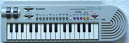
Casio GZ-5 |
+ | 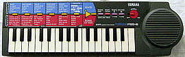
Yamaha PSS-6 |
= | 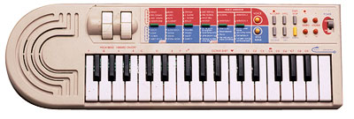
Medeli MC-2001 |
This also makes it such difficult to identify who really manufactured or created a Chinese no-name trash tablehooter, since they all exchange hardware designs and components, use fantasy names and independently develop their works into multiple directions.
Antonelli made mainly fullsize home organs and released only few different home keyboard models, but these always were somewhat different than other brands and often had unusual accompaniment features. Most of their analogue keyboards are rare; according to their only 3 or 4 digit short serial numbers of most models only a few hundred or thousand specimen were made. Other models have here 2 short numbers separated by a "/", those may indicate production week (or month) and number of the specimen in that week (or month). The sheet metal model plates at their case bottom look exactly like with Siel keyboards, and also ICs and PCB stamps in some Antonelli instruments are labelled "Siel", which was likely a different brand label of the same company to market their more professional instruments. E.g. the Antonelli 2381 was also released as Siel MK 370, and the Antonelli 2614 as Wersi X1000, thus Siel and Wersi organ repair companies may also help to retrieve spare parts for the rare Antonelli stuff. Also the hardware of Madison OK 500 strongly resembles late Antonelli keyboards. Generally Italian keyboards made in 1980th and 90th share a lot of parts and construction details, so e.g. also Farfisa, Bontempi, Baleani, Commander, Keytek, Orla, Suzuki Keyman etc. had similar PCBs, sound ICs, key mechs etc. So far I know, Antonelli and Bontempi later joined with Farfisa. I was told by e-mail that Siel was the actual mother company that manufactured the Antonelli keyboards. Siel later released professional wavetable synths under the Keytek brand and their Italian factory was finally bought by Roland.
caution: A common disease of Antonelli and related Italian 1980th keyboards is that the plasticizer of PVC mains cables melts itself into their grey case plastic, which looks like scratches by a hot soldering iron and locally turns the plastic surface and paint into tar- like goo. Thus watch out to avoid direct contact between plastic case and any sticky or smeary feeling PVC cables. (Better generally avoid contact with soft PVC; also certain keyboard dust covers and -bags were made of the plasticized material.) Especially the fixed mains cables of first generation Antonelli keyboards (with bulky case) seem to contain particularly aggressive plasticizers. The over 20 year old cable of my Syntorgan 2445 still feels softer than many brand new cables (and slightly smeary), while its silver grey case was disfigured by a zillion of black burn marks, those linear pattern indicate that they obviously were caused by the cable. The smeary goo residues on the case can be partly removed with vegetable oil, but be careful to wash off also the oil residues with water and dish washing detergent, since long oil contact may damage this vulnerable plastic also.
Antonelli used for most instrument models only plain numbers instead of letter combinations.
With Bontempi (see links)
the prefix scheme of old keyboards is very messy and especially the same
keyboards were released with very different prefixes. Specific for older
Bontempi instruments is also that on the model plate the ciphers behind
the dot indicate the case style (i.e. e.g. a. Bontempi HF222.21
and HF222.22 differ only in the case colour).
| BK | = "Basic Keyboard" old mini keys |
| HF | = "High Fuga" old fullsize keys |
| HP, KF, KP | = home organ |
| M, MS | = old fullsize keys, squarewave without rhythm |
| HIT | = fullsize toy- like keyboard |
| HT | = ? |
| BN, PK | = midsize chord organ |
| ES | = "Europa Series" fullsize analogue or midsize digital toy keyboard |
| MR | = midsize with LCD (only MR52 Special known) |
| B, X, HB, MRS | = almost everything without logical scheme |
| BS | = "Bontempi Synth" midsize toy synth |
| KE | = "OnTour" midsize toy keyboard/ synth |
| ET | = old System5 mini keys (only ET-202 known) |
| KM | = "KidsMusic" old System5 midsize keys (only KM40 known) |
| KS | = old System5 midsize or fullsize keys |
| BT | = old System5 midsize or fullsize keys |
| AX, RX | = fullsize e-piano |
| AZ | = old fullsize professional MIDI keyboard |
| AT | = System5+ midsize or fullsize keys |
| KT | = System5+ midsize keys (only KT-32 known) |
| GT | = cheap System5+ keyboard (no MIDI) |
| PM | = "ProfiMusic" System5+ fullsize keys with MIDI or GM |
| NK | = fullsize keys with GM |
| SK | = modern toy keyboard |
| KI, MK | = modern cheap toy keyboard (Yongmei etc.) |
Early 1980th Bontempis had only few preset sounds, but with quite nice analogue timbres and percussion. Regard that the first ones (e.g. Minstrel Beta) had for all polyphony channels only one monophonic common piano envelope which behaves like the Hammond organ "percussion" feature, i.e. all held notes sound again when an additional piano note is played. Other such models (e.g. Eclipse) even delayed additional notes, so they should be rather considered monophonic with polyphonic accompaniment than genuine polyphonic instruments. Later analogue models work well without such flaws.
In mid of 1980th Bontempi started to release very poor sounding digital keyboards with boring static waveforms, primitive volume envelopes, very grainy digital percussion, lots of DAC aliasing noise and way too loud yelling tinny speakers combined with a coarse digital volume control that at bearably low setting ate even more of the already low bit resolution. Most of these tablehooters had green drum/ chord pads and green and yellow control panel writing. Only with the 666 sounds models (mixed from 36 basic sounds resulting in nicely complex virtual analogue timbres, later called System5+) digital Bontempis became better again. So unless you know that you want them, it is wise to skip the green series (except 666 sounds models like PM61 or KM40). Another nasty trap by Bontempi was that when MIDI became popular, they coined the almost fraudulent advertisement term "midi keys" for midsize keys and this way sold them as "digital midi keyboard" despite the affected cheap tablehooters keyboards had absolutely nothing to do with MIDI. Generally digital Bontempi sound bank keyboards can be a little awkward to use, because many features are controlled by typing numbers on a keypad instead of OBS buttons. Also their accompaniment tends to be stubborn (can not be muted etc.). Most 666 sounds models except PM61 and PM61/S have the same or at least very similar preset sounds. Bontempi also released a few rare "100 sounds" models (polyphonic with blue pads) those are basically only renamed 666 sounds models and thus share the same nice sound engine. The CPUs of late single-chip Bontempis were strictly tailored for the particular keyboard model and so lack interesting matrix eastereggs; especially there are no hidden keyboard octaves, additional drumpad inputs (during rhythm combined pads become chord buttons) or accompaniment variants. Models with less than 49 keys even lack a keyboard matrix and simply use one pin per key or button to avoid diodes. But some keyboards with mono amp have a CPU with stereo output.
Because in the 2nd half of 1980th Bontempi joined with Farfisa, they shared a lot of hardware. Many people don't know this and so on eBay pay crazy prices for unknown digital Farfisa home keyboards because they imagine them to be something "professional" despite they contain the same hardware like much cheaper common household Bontempis. Often the Farfisa model even lacks features (e.g. drumpads or sequencer buttons) found in their Bontempi counterpart (so look for matrix eastereggs in the crippled models). Musically most exciting (at least for live performance) are the professional Bontempi AZ-series keyboards, those had versatile accompaniment or even basic synthesizer features and MIDI. At the other end the small BS and KE-series toy synths have a lot of wicked grainy siren timbres those are nice for tekkno. Also the 666 sounds models have some freakish timbres those can be seen as a cheap alternative to Casio CZ synths; the GT-770 was even an improved variant with 100 basic sounds. Unfortunately all keyboard based on it lack MIDI.
I haven't fully understood the Bontempi IC naming convention. At least with 1990th digital home keyboards the software number of the internal ROM seems to be the number behind "COMUS" (often 3rd row), while the chip type is alphanumeric (e.g. "A45016PH", usually 1st row). But yet I found no CPU with same type but different COMUS number, so I suspect that also the last digits of the CPU type include the software number (e.g. "A45016PH" = CPU "A45" with software number 016). Many of their CPUs may be generic Texas Instruments microcontrollers with internal ROM, running a softsynth on a chip. Unlike Casio, Bontempi seems to hide eastereggs much better, because instead of fixed keyboard matrix diodes they tend to use configuration pins wired to GND or +Vs. So unless there is a jumper or printed PCB mark visible, it makes it next to impossible to recognize which of the many supply voltage or GND pins of a large SMD IC has genuinely a hidden meaning. (E.g. in BS 2010 hardware such a mode select pin switches between 2000 and 3000 sound combinations.)
Since about 2000 Bontempi has started to spoil their name with selling plenty of rebranded cheap Chinese toy trash including Potex and Yongmei grade toy tablehooters those partly have even polyphony bugs. These are no authentic creations by Bontempi/ Farfisa anymore and so have nothing to do with their classic sound engines.
Casio (see links) has a little messy naming scheme; especially some CT-# keyboards were later released as CTK-#, some SA-# as M-# and various toy keyboards had own names. With early keyboards a by 1 higher number often stands simply for a different case colour variant (e.g. brown instead of white).
old keyboards:
| CT- | = "Casiotone" fullsize keys (the first keyboards were named "Casiotone #" instead of CT-#") |
| MT- | = midsize keys |
| PT- | = "Petite Keyboard"(?) mini keys |
| VL- | = "VL-Tone" (named after "Very Large Scale Integration" ICs) early mini keyboards |
| EP- | = toy keyboard |
| SK- | = "Sampletone" sampling keyboard |
| CK-, KX- | = keyboard with built-in radio and/ or cassette recorder |
| DM- | = midsize dual manual (only DM-100 known) |
| AZ | = keytar (guitar shaped keyboard) |
| CZ-, | = "CosmosynthesiZer"(?) phase distortion synthesizers (improved FM) |
| VZ- | = interactive phase distortion synthesizers (improved FM) |
| HT-, HZ- | = "Spectrum-Dynamics synthesis" semi-analogue synthesizers |
| FZ- | = professional sampler (contain also phase distortion synthesis) |
| RZ- | = drum computer |
| CPS | = e-piano (velocity sensitive fullsize keys) |
| CSM- | = MIDI tone generator module |
| DG-, PG- | = synth guitar |
| DH- | = "Digital Horn" MIDI saxophone |
newer (sample based) "ToneBank" keyboards:
| CTK- | = "CasioTone Keyboard" expensive fullsize keyboard |
| CA- | = cheap fullsize keyboard (no MIDI, only mono?) |
| MA- | = midsize keys (MA-1..10 = melody alarm clocks) |
| SA- | = small keyboard (up to 37 mini or midsize keys) |
| M- | = "Casio Club" like SA-series, but M-10 is much older without samples |
| KA-, PA- | = toy keyboard |
| RAP- | = "Rapman" DJ toy instrument |
| DJ- | = DJ toy keyboard with cassette recorder |
| TA- | = toy keyboard with cassette player (only TA-10 known, TA-1 = data tape storage cartridge, TA-1000 = talking calculator) |
| KT- | = keyboard with built-in radio, cassette recorder and/ or CD player |
| AT- | = fullsize oriental keyboard |
| LK- | = fullsize key lighting keyboard |
| ML- | = key lighting mini keyboard (or 1980th melody calculator) |
| VA- | = "Voice Arranger" midsize effect keyboard (only VA-10 known) |
| GZ- | = MIDI master keyboard |
| PMP- | = velocity sensitive fullsize keys |
| PS-, PX- | = e-piano (velocity sensitive fullsize keys) |
| AL-, PL- | = key lighting e-piano (velocity sensitive fullsize keys) |
| AP- | = heavy wooden e-piano (velocity sensitive fullsize keys) |
| WK- | = "workstation keyboard"(?) velocity sensitive fullsize MIDI keyboard |
| MZ- | = professional fullsize MIDI workstation keyboard |
| LD | = e-drumkit |
With fullsize keyboards there may be also some other prefixes but I don't care much about them. Also some other exotic names may exist. A general rule of thumb is that Casio instruments with names ending on "-1" (like VL-1, SK-1 etc.) are usually good ones (except perhaps PT-1) and particularly those ending on "Z-1" are great. Apparently all old Casio instruments (before CTK- series) with an "8" in their type number had a ROM-Pack slot and key lighting. The only known exception is the keyboard CT-8000, which was part of the ultra-rare modular stage organ Symphonytron 8000.
The first important thing to know is - there is no such thing like a "fully analogue" Casio keyboard.
Vendors those claim that on eBay either attempt to fraud you or don't know it better. Even the earliest Casio instruments employed for their main voice always digital tone generators with digital volume envelope. In the opposite Casio even invented the digital sound bank concept. Only timbre filters, accompaniment- and percussion envelopes and partly percussion sound generators were analogue in early Casio keyboards, but there never were VCO. May be this false myth originated also from the very high internal mixing and DAC output frequency of about 0.5 MHz in early models, which prevents glassy digitallic aliasing noise and combined with high DAC resolution (with sound IC D931C up to 17 bit) results in high tone quality with warm timbres associated with classic analogue synths. Casio also employed analogue sound channel mixing in all keyboards before MT-540 (1988), which makes these easy to upgrade with separate sound outputs or insert-effects. Also the capability to play very short blip notes (later prevented to "improve" midi playback) and responsiveness by unusually low latency (thanks hardware multitasking with sound channel switching at full clock rate and fast keyboard matrix scan at some kHz) gives first generation Casios the direct feeling of analogue hardware. In sample based instruments Casio spent much work on sophisticated interpolation algorithms for smooth pitch shifting without digitallic overtones, which makes even early models like SK-1 (which does contain envelope VCA) still sound warmer than many modern Chinese toy tablehooters, which may be falsely explained with analogue timbre processing.
The Casio jargon for sound synthesis engine is "sound source". The different engines have cryptic 2 or 3 letter abbreviations proudly mentioned in ads, but with exception of some professional synthesizers the deeper meaning and inner working was hidden from customers (not even told in service manuals). So many of these may be rather advertisement buzzwords than technologies, enshrouding that they were just minor variations of older sound engines. This list is likely inaccurate, because many old or low grade sound sources were not mentioned anywhere, so I only added them from own hardware examination. Also with modern models (large compressed samples) and pianos I am no expert. The IXA sound source (CTK-1000 from 1993) was the last engine with many classic synthesized sounds (now even with velocity and some editable parameters), although it already lacks the famous (SA-series) program loop synthesis preset sounds with complex algorithmic envelopes. After IXA Casio dropped the use of synthesized preset sounds in favour for long wavetable samples imitating natural instruments, which IMO makes newer keyboards mostly boring. With the HPSS sound source from 2013 (XW-G1 synth) fortunately a new versatile synth engine came out, which however does not fully include older (e.g. PD) synth algorithms. This list is sorted by technology rather than release date.
List of Casio sound sources:
| sound source | full name | 1st use | notes & features | year |
| plain squarewave | ||||
| ? | ML-80 | monophonic squarewave (1:1, 100% tremolo) | 1979 | |
| ? | ML-81 | monophonic squarewave (1:1) with decay envelope | 1980 | |
| multipulse squarewave | ||||
| ? | VL-1 | monophonic multipulse squarewave with switchable fixed filter. | 1981 | |
| ? | PT-20 | like VL-1 with obligato + chord/bass voice. | 1982 | |
| ? | MT-11 | 2 layered bipolar multipulse squarewaves with switchable fixed filter. | 1983(?) | |
| ? | MT-200 | bipolar multipulse squarewave with switchable fixed filter. | 1984(?) | |
| stairwave | ||||
| CV | Consonant-Vowel synthesis | CT-201 | 2 mixed stairwaves with switchable fixed filter. CT-201 & 202 layer 2 such sound CPUs with each a filter. | 1980 |
| ? | VL-5 | only 1 stairwave with switchable fixed filter (very different hardware). | 1982(?) | |
| ? | MT-65 | programmable CV (sound IC with external CPU). | 1983 | |
| ? | CT-6000 | velocity sensitive CV variant (layering 3 sound ICs). | 1984 | |
| SD | Spectrum-Dynamics synthesis | HT-series | user programmable CV variant with VCF for synthesizers. | 1987 |
| additive synthesis | ||||
| ? | 1000p | additive synthesis (5 layered sinewaves, sounds drawbar-like). | 1981 | |
| Phase Distortion (FM) | ||||
| PD | Phase Distortion | CZ-series | Casio's FM synthesis variant. | 1984 |
| iPD | Interactive Phase Distortion | VZ-series | PD successor with programmable routing. | 1988 |
| speech synth | ||||
| ? | TA-1000 | data-reduced speech synthesis (LPC based?, PARCOR?) | 1983(?) | |
| sampler | ||||
| ? | SK-series | lofi sampler (SK-1 has also drawbar softsynth). | 1986 | |
| ? | FZ-series | 16 bit sampling synthesizer. | 1987 | |
| ? | SK-60 | lofi sampler on different PCM engine hardware. | 1996 | |
| software based (wavetable + multiple synth algorithms) | ||||
| PCM | Pulse Code Modulation | various,
e.g. SA-series |
Casio wavetable softsynth on a chip, including many other synth algorithms like FM variants or program loop synthesis. The generic term "PCM" was earlier used for anything sample based (e.g. Casio percussion ICs). | 1988 |
| CD | Casio Digital ? | MT-540 | PCM engine version with external 16 bit sample ROM. | 1988 |
| Super CD | ? | CT-770(?) | PCM engine version with velocity, effect DSP (external 16 bit sample ROM). | |
| AP | ? | AP-7 | PCM engine version with velocity, used in first Celviano piano. | 1991 |
| ? | VA-10 | PCM engine version with effect DSP + Harmony Arranger. | 1992 | |
| IXA | Integrated Cross-Sound Architecture | CTK-1000 | PCM engine version with velocity, multisamples, effect DSP (external 16 bit sample ROM | last engine with many synthesized classic "PCM" sounds). | 1993 |
| A2 | A² (A-square) | wavetable with sample compression + effect DSP. | ||
| HL | Highly compressed Large waveform | A2 successor? | ||
| ZPI | Zygotech Polynomial Interpolation | MZ-2000 | IXA successor(?) with special sample morphing. | 2000 |
| AHL | Acoustic & Highly-compressed Large-waveform | CTK-4000 | HL successor with acoustic instrument multisamples. | 2008 |
| AIF | Acoustic & Intelligent Filtering System | Privia | piano simulation | 2009 |
| AiR | Acoustic and Intelligent Resonator | Privia | piano simulation | 2013 |
| HPSS | Hybrid Processing Sound Source | XW-G1 | PCM engine successor for versatile synthesizer (partially hardware based). | 2013 |
Casio service manuals are unsuited to identify keyboard matrix eastereggs, because they generally stay silent about matrix places not used in the described model. (But in the opposite you can of course skip all its documented matrix features to concentrate on the blank areas.) Unlike Yamaha, Casio is generally infamous for secrecy about the inner working of even their oldest and most outdated keyboard ICs. There is absolutely no cross-reference manual; perhaps driven by fear of patent lawsuits they had lost several times, they never published datasheets nor sold individual sound ICs (only complete instrument designs) to 3rd party manufacturers. Another plausible reason may be, that to be the first in competition, Casio apparently often released products based on new inventions before they had finished patenting them. Thus service manuals typically don't explain more about Casio special ICs than barely necessary to identify a faulty one. At least IC pin names in later schematics stay complete, although unused ones often lack description, and sometimes Engrish gibber exchanges similar characters or even words. (Things like confusing "base" (a drum) with "bass" (an accompaniment voice) or "cymbal" with "symbol" can make functions really hard to understand, which only clears up by tracking wiring in schematics or even the actual hardware.) So you can only learn to read between the lines and compare manuals of multiple similar models to find out more. When necessary, I therefore attempt to use plausible function names instead of their gibber.
But to learn more about the inner working, it is more useful to websearch for Casio patents with "priority date" close to the release date of the instrument you are looking for. Unfortunately patent names are often very generic or even grossly misleading (e.g. "System for generating sample tones on an electronic musical instrument" is about playing a demo note during preset sound selection, which has absolutely nothing to do with sound sampling) and the interesting parts are often not even that what is patented, but technical details about other parts of a described instrument. The disclosed reference implementation often also differs from the actual finished product, which can make it hard to identify the actual instrument and to figure out how it functions. But patent texts are the only officially published technical documents about Casio hardware those can be found online in large quantities, which makes them worth to look into even though they can be hard to understand. Because one purpose of patent texts is legally documenting the state of art of already known inventions (to prevent patenting twice), unlike websites they are not prone to suddenly disappear. So not every hobbyist website or forum talking about them is in the need of keeping backups online (telling a patent number is better than an URL). Patent texts can be hard to understand, but often they are the only traces that orphan hardware left in the noosphere. It is on us now to find out and index what they are about. There is are a huge online archive of unidentified technical information out there, that is useful far beyond the realms of companies and lawyers.
This Chinese shanzhai company made the most bizarre whacky toy tablehooters straight after Yongmei. Typical for them is especially that they blatantly imitated case design or sound samples from other known keyboard brands, and that many of their products had hardware bugs and absurd funky model names full of Engrish misspellings (often containing the word "luxury", see JX-20165 for more info). The case plastic seems to be similarly flimsy like early Yongmei instruments, and also the case paint scratches easily, thus be careful with sending them through mail. At least in Germany most of their instruments are rare, and also the rest is at least uncommon. Jin Xin Toys apparently later renamed itself J.X.T and released under this label the strange toy groovebox J.X.T 20808.
Instrument model numbers of this company often have the prefixes JX-, JT-, J.X.T. Some of them were also released by Interkobo.
Kawai released only few small keyboards and mainly professional
and semi- professional stuff; there may be many other prefixes I haven't
listed here.
| FS, X | = velocity sensitive fullsize MIDI keyboard |
| WK | = fullsize MIDI keyboard |
| MS | = midsize keyboard |
| PH | = "pop synth" MIDI keyboard (only PH50 known) |
| *m | = MIDI tone generator module (name ending on "m", number is often the same like the keyboard version) |
| SX- | = analogue synthesizer |
| K | = digital synthesizer |
| Z | = professional fullsize MIDI workstation keyboard |
| MDK | = "MIDI Datacat" midsize MIDI master keyboard |
| R- | = drum computer |
| GB- | = "session trainer" (portable accompaniment workstation) |
| E-, RS- | = home organ |
Most interesting with Kawai beginners keyboards is their versatile accompaniment feature "One-Finger Ad-Lib".
This Chinese manufacturer (see links) builds the most noble and stylish looking toy instruments I ever saw. Especially they make very impressive toy DJ and tekkno consoles (see e.g. Mix Evolution); despite also their toys have some flaws (e.g. no sound output, some have wrong pitch or lack matrix diodes), Potex seems to be yet the only toy company with the right feeling for the sound and estheticism of the tekkno environment. Some of their instruments were also released with the brand names Beat Square, Kid's Com/ Happy People, Kawasaki. (Someone e-mailed that versions of their Super Jam keyboard were also labelled DSI/ Yamaha Motorcycles and possibly Oregon Scientific.) Potex instruments seem to have rather names than a specific model number pattern. Typical features to recognize them are a "demo/play" switch (changes auto-power-off duration) at the case bottom and often the annoying auto-power-on feature, which turns it on (wastes battery) by any accidental key press. Some have a transparent coloured control panel.
This Hong Kong company made toy and small beginners keyboards, including some with interesting full polyphonic mixed squarewave timbres and analogue percussion (like Ramasio 892 aka RJP 896) those sound very 1970th homeorgan-like. In 1970th they also made LED pocket calculators and apparently later only released toy keyboards and various calculator-like (e.g. pocket databank) LCD devices. Non-toy keyboards were only made for a short time. They also used the brand names Ramasio and Star Mate.
Regard that the rubber contacts in these keyboards are not of silicone but something that resembles cheap Chinese hot water bottle (butyl?) rubber, and tend to stick and decompose (turn white and brittle), particularly if crushed (keys held down during storage by objects etc.) or exposed to UV light or airborn chemicals like ozone, oil or battery leak vapours. Thus it is a good idea to store these instruments without battery in an airtight PE plastic bag away from sunlight.
With Yamaha (see links) there are way less prefixes, although some PS-# PortaSound keyboards were later released as PSS-#. Often identical Keyboards were later re- released with a different (usually lower) number (and different control panel colours).
old keyboards:
| PS, PS- | = midsize or fullsize keyboard |
| A, B, C, D-, E, CN-, CSY-, FC, FE, FS, HC | = home organ |
| CP | = e-piano (velocity sensitive fullsize keys) |
| CS, CS- | = analogue (later virtual analogue) synth (but CS40 is a new wood guitar and even mopeds began with CS) |
| GS- | = preset FM synthesizer |
| SK | = "string ensemble keyboard" (fullsize) |
| YC- | = stage organ |
Later keyboards have the following scheme:
| PSR- | = fullsize keys |
| PSS- | = "PortaSound" midsize or mini keys |
| VSS- | = "voice sampler" sampling keyboard |
| HS- | = "HandySound" old mini keyboard (or home organ) |
| SHS- | = "Sholkey" (shoulder keyboard ) = guitar shape keyboard aka keytar |
| MK- | = midsize synth keyboard (only MK-100known) |
| PC-, PCS- | = "PlayCard" midsize key lighting keyboard |
| TYU- | = mini key lighting keyboard |
| EZ- | = fullsize key lighting keyboard |
| KB- | = fullsize "ensemble" keyboard |
| MP- | = midsize with score printer (only MP-1 known) |
| DX | = professional FM synthesizer |
| SY | = improved FM synth workstation |
| YS | = cheap FM synthesizer |
| QR-, QY- | = portable mini workstation |
| MC- | = home organ |
| HC-, ME-, MW, | = stage organ/ transportable home organ |
| DD- | = "digital drumkit" e-drumkit |
| PF, YPR- | = e-piano (velocity sensitive fullsize keys) |
Unlike Casio, Yamaha introduced fully digital sound processing already in 1982; their last analogue keyboards were PS-1, PS-2, PS-3, PS-10, PS-20, PS-30. Basically everything later mixes sound channels digitally and outputs them through one common DAC, which makes upgrades with separate sound outputs or insert-effects much more difficult. Particularly early Yamaha sound ICs often contain the complete preset sound definitions pre-programmed in internal ROM, and the protocol only selects a sound number but does not support setting synth parameters individually, which makes it impossible to program own sounds on them.
A benefit of Yamaha is that they keep the user manuals of all their instruments (even oldest home keyboards) online on their website. If you want to websearch for keyboard patents, regard that the official early company name for musical instruments was Nippon Gakki, not Yamaha. Unlike Casio, Yamaha patented rather individual functions or technical details than entire instruments, which makes it hard to identify which patent describes which keyboard. This may have to do with that Yamaha also sold their sound ICs separately to manufacturers of home computers, videogames, PC sound cards and other musical instrument companies. Otherwise Yamaha keyboard service manuals explain the inner working more detailedly than Casio's; unfortunately beside those of analogue synths, only very few found their way yet on hobbyist websites.
Since mid of 1980th most Yamaha keyboards include a hidden service mode easteregg (the "test program") that can be accessed by holding 2 keys (usually the rightmost or sometimes leftmost 2 whites) during power-on. It will quickly test its ROM and RAM and then go into a keyboard matrix test, where all keys, panel buttons and even digital switches play different notes (in a fixed timbre) and sometimes other distinct sounds. Sometimes these even may be useful as a keyboard drumkit mode. Buttons with LEDs will light/ unlight them when pressed, and in devices with display some keys or buttons also show corresponding ciphers to test all digits. More complex instruments may erase battery backed-up memory during self-test, thus avoid to play around with it so long it contains important data. The service mode can be also of great help to write down the keyboard matrix (particularly of panel buttons), however you still need to verify your examination in normal mode, because the test tones can be ambiguous (i.e. unused matrix places may have all the same pitch like a panel button, or buttons and keys sound the same).
On Yamaha ICs the production date in 1980th was encoded like this:
YM2163
79 28 85 G
block 1: "7" for lower digit of year (here 1987), "9" for number of
month (here September. October, November, December correspond to "X", "Y",
"Z")
block 2: "28" means day in the month.
block 3: "85" is lot number, and last character "G" is factory code.
So the example means "produced on 28. September 1987; Lot No.85 of factory
G".
After 1990 the encoding changed into 2 blocks of 4 digits:
2-digits of block 1 means lower digit of year, following 2-digits means week in the year. First character of block 2 means factory code (same as 2-digit version), others are Yamaha internal lot code. (Thanks Saien Mado for info.)
In Yamaha service manuals, the same IC is often referred in different sections by different names. The software number here seems to be the part number in the "electrical parts" section, while the additional number in the "description" field refers to the more generic hardware type. The part numbers end on an additional digit, that when zero is not printed on the component itself but apparently only is a revision number or fills the entry to a certain length. (So e.g. Yamaha PSS-80 and PSS-125 both have a CPU with description "HD6305V0***P", but the part number for PSS-80 is "XF877B00" while PSS-125 has "XG724B00" due to changed software. On the IC package is stamped "XF877B0", without the rightmost "0". Also other digits can be omitted, so the PSS-100 CPU in description field is "HD63A01YORH98P", but IC is stamped only "3A1YORH98P".)
Yongmei (shanzhai trash keyboards)
Yongmei (website) is a Chinese "no-name" company that in former times made the likely worst keyboards of the world; despite modern looking case design these only contained a monophonic transistor beep tone generator (see Golden Camel 7A for info). But nowadays they also sell better keyboards, including even velocity sensitive MIDI instruments (seen on their site and eBay), but at least the cheaper fullsize instruments I bought in 2006 were still ridiculously bad and e.g. have fraudulent duplicate sound/ rhythm names, severe polyphony bugs by omitted key matrix diodes and the flimsy plastic stank extremely of acrid chemicals (see e.g. Yongmei DL-2300, YM-3300, YM-6700). Because Yongmei buys their components from different manufacturers (their own factory seems to be Meisheng) and apparently sells their stuff under many trade names, it is hard to track which instruments were made by them. The situation is a similar mess like with famiclone game consoles. So it may be that I use the term "Yongmei" here a bit too generic for all trashy Chinese shanzhai tablehooters built like this. Some companies also sell as well Yongmei as other keyboards under the same trade name, and not least the huge variety of case variants makes it hard to estimate whether expensive and well working apparent Yongmei keyboards may be in fact rebranded products made e.g. by Medeli (a Chinese manufacturer of very reasonable build quality). Although due to shanzhaiism also hybrids between Yongmei and Medeli parts (robust case with lousy PCB or vice versa) may exist, in practise this doesn't seem to happen; by my observation the haptic and functional quality is always either one or the other; the difference is blatant.
The following list of prefixes and keyboard trade names IMO hint to shanzhai manufacturers likely associated with Yongmei. The right column of this list coarsely indicates the typical keyboard hardware generations related to that prefix. Transistor tooters and transition Yongmeis (see below) of course never had display nor midi, while the other types can have combinations of features (sound generator is always polyphonic, midi ones tend to have a display etc.). This list was compiled by visual and feature comparison (mostly eBay pages); as a work of personal opinion it is in no way claimed to be error-free nor all-comprehensive, but only intended as a brief overview about the wide spread of such hardware.
Independent from fantasy brand logos, apparently all keyboards with
YM- are Yongmei and with MQ- are Shengle. These prefixes were not used
by other (particularly no quality brand) manufacturers.
| YM-, YMS- | = Yongmei | t, tr, p, led, l, m, gm, u, kl |
| MS-, MK-, MLS- | = Meisheng (aka Miles, Meike, MeiKe, Meiker), MS- is also used by Yongmei, Music Fairy | t, tr, p, led, l, m, gm, u |
| JY- | = Jia-Yin, also used by Yongmei, GN | t, p |
| SK- | = Sankai (has no rhombic SK logo) | p, led |
| A | = ? | l |
| AB | = used by Keytone | p, led |
| AD | = used by Yongmei itself? | led |
| ARK- | = Aierke, also used by Echo, FunKey, Tetratone | l, led, m, gm, o |
| AWO | = used by Ayoub | l, gm?, o |
| BD- | = used by Lommer | led |
| BF- | = Bigfun | p |
| BK- | = used by McGrey | led, l |
| CEK-, CHP- | = used by Cronenwerth | led, l, m, gm |
| CK- | = used by Delson, Ringway | led, l, m |
| DL- | = used by Yongmei itself? | led |
| DRM- | = Dorimei | l, m, gm |
| FW | = used by PlayOn | l |
| G | = used by Divarte | led |
| GA- | = Jinjiang Shengle Toys, used by Music Fairy (coloured toy keyboards) | p, led |
| GC- | = Golden Camel (released by Meisheng?, my 11ABhas a Miles sticker, my 7A box has the logo Sunny) | t, tr |
| HCK- | = ? | p |
| HD- | = used by Little Angel, Shining Star | t |
| HEP- | = used by Hricane | led |
| HL- | = used by Canto (additional Bandstand label on box, like MQ-) | p, led |
| HMP- | = First Act, Power Key, Smart Keyboard, SongMax | p |
| HS- | = Boogie Bee, Jinruche, Tobar, Toi-Toys | p |
| HY- | = used by Ocamo | p, led |
| JC- | = Jing Cai, used by Elegance, V-Tech (fake?) | p, led, l, gm |
| JK- | = ? | p, led |
| JL | = Jinle | t |
| JSD- | = ? (Chinese language, like Bandstand MQ-) | p |
| JT- | = Jin Xin Toys ?? (keyboard name with "Lucury") | led, l, m |
| K | = used by IMD Musik, Ringway | led, l, m |
| KB | = used by DEMA, Huntington | t, led |
| KBX- | = used by Paxton | led, l, m, gm |
| Key- | = used by Roxxy | l |
| KT- | = ? | p |
| KX- | = used by iDance, Orla (only cheaper modern keyboards, may be EK- hardware) | led, lcd, gm, o |
| LH- | = Diamond | l, gm |
| LK- | = used by McGrey (only key lighting) | l, kl |
| LP | = L&P, also used by Auna, C.Aemon, C.Giant?, Clifton, Schubert, Streetlife | p, l, gm, u |
| LS- | = used by iBurswood | led |
| LXF- | = ? (Chinese language, like Bandstand MQ-) | p |
| M | = used by Clifton | |
| MEK- | = used by Ibiza | led, l, gm, u |
| MI | = used by First Act | l |
| MIK- | = used by Karcher | l, m |
| MK (others) | = also used by Acoustic Solutions, Akita, C.Aemon, Carsan, CBSKY, DynaSun, FW Studio, Gear4Music, IMD, Lagrima, Ligneous Digital, McCrypt, Medeli (modern midsize), Mirage, Saisho (unrelated), Santander, SIEL (unrelated), Skytec, Sonart, StarSound, Startone, Streetlife, Orla (midsize, EK-hardware), Vangoa | p, led, l, gm, u, kl |
| MPW | = used by EagleTone | l, m, u |
| MQ-, MQ, QM | = Jinjiang Shengle Toys, used by Bandstand, BSD, Drfeify?, Fairy, Let's Enjoy Music, Music Fairy, Music Good, Music Paradise, my Music, Ouda, Renfox, Shengle, Sound Master, Wostoo | p, led, l |
| MSD- | = ? | p |
| MX | = Maxwell | led, m |
| ?N | = ? | led |
| NJS | = New Jersey Sound | led, u |
| PK- | = used by McGrey (only expensive models) | l, u |
| PN- | = used by Auna | l, gm |
| PS- | = Panashiba | t |
| QS- | = ? (case design like MQ-) | led |
| RJ | = RockJam | l |
| RL- | = used by Renkforce (repackaged MK-) | l, u |
| S | = used by Meike | t |
| S- | = used by IMD Musik | led, l, gm |
| SD-, SD | = Shan Dou, used by Bandstand, Lucky Bear | p, led |
| SK- (others) | = Shenkang/ ShenKong/ ShenHong?/ Shengang? (has rhombic SK logo), also used by Yongmei, HMO, Keytone, Santander, SongMax | t, tr, p, led, l |
| SLM- | = used by Clifton | p |
| SWT- (others) | = Siweite, Sieweit (only MIDI keyboards?), also used by Yongmei | led, l, m, gm |
| T | = used by Axman | led |
| T (also TTT?) | = Tetratone | led, l, gm, u |
| TB | = used by Ringway (big, pitch + mod wheel) | l |
| TLF- | = ? | p |
| TS- | = used by Joy | p |
| TX- | = Tong Xin Toys | t, p |
| VGK- | = Vangoa | gm, led, l, kl, u |
| W | = used by Keytone (only highend MIDI keyboards?) | l, gm |
| XH- | = used by Miles, Kamichi, Ostoy | t, tr |
| XTS- | = used by Angelet | led |
| XW- | = Xiong Wei, also used by Yongmei | t, p |
| XY- | = Xin Yun | led, l |
| YCY- | = Sanmersen (like MQ-?, fake Casio SA-46) | l |
| ? | = Groovy Tunes | t |
| ? | = Hricane (like MQ-?) | led |
| ? | = Huntington | led |
| ? | = Interkobo | t, p |
| ? | = Maestro | p |
| ? | = Music Machine Electronic | t |
| ? | = Play On (Toys'R'Us) | p, led, l |
| ? | = Skytronic | led, gm |
| ? | = Techno-Beat | p |
| ? | = Teorema | p |
| ? | = Trendshop | led |
| ? | = Toyman | l |
| ? | = Canto (additional Miles label) | p |
| numbers | = used by Carsan | t, tr, p, led |
| numbers | = used by Canto | p |
| numbers | = used by Goldtronic, Pro-Sound | led |
| numbers | = used by LiJin (like MQ-) | p, led |
| numbers | = used by reig (like MQ-, additional concerto label) | led |
| numbers | = used by Schubert | l |
| numbers | = used by SS Music | p |
| numbers | = used by StarMate | t |
| numbers | = used by Super-TS | t |
| numbers | = used by Weinberger | led, l, gm |
| numbers + letter | = used by H+S, Yongmei | p, l, led |
| names | = used by eGroovz | t, led |
| names | = used by GrooveBeat | p |
| names? | = used by lionelo (like MQ-) | l |
| names? | = used by Rongfa | p |
| names? | = used by DigiTone, EracMusic, FW Studio | p, led |
| various | = additionally on box by FunKey | p, led, l, m, gm, u |
keyboard generations (right column):
| t | = transistor tooter (or monophonic IC) |
| tr | = transition Yongmei (slide switches + digital main voice or rhythm) |
| p | = polyphonic (no display) |
| led | = LED display |
| l | = LCD display |
| m | = midi (less than gm) |
| gm | = General Midi (128 preset sounds or better) |
| u | = USB midi (not only MP3 player) |
| kl | = key lighting |
| o | = oriental keyboard |
Very important with these keyboards is that the number seems to indicate only the case shape, while a following letter stands for the hardware revision number. Thus keyboards with identically looking case can contain totally different hardware; the higher the letter, the later the hardware version. Thus a hypothetical YM-1234 (I don't know if it exists) may contain a monophonic transistor beep tone generator, while YM-1234A has a monophonic sound chip with separate rhythm IC and a YM-1234B contains a 2 note polyphonic My Music Center variant or the like. Another strong hint to Yongmei or Sankai related hardware is when a keyboard with plastic case has the odd count of 54 fullsize keys; other companies only released keyboards with either 49 or 61 fullsize keys, but I newer saw 54 keys on instruments by any other known brand. Also keyboards with green percussion icons on the rightmost or leftmost keys are typical for Yongmei, because they often have built a CPU into a case with more keys than that CPU can support (thinking bigger is better...) and wired the remaining keys parallel with drumpad buttons to camouflage the mismatching combination. With Sankai I am not sure if they are identical with ShenKong (aka Shenkang / ShenHong??); both employ the 'SK-' prefix, but only the latter has additionally a rhombic 'SK' logo, which I never saw on 'Sankai' branded keyboards despite the rhombic logo already existed at the same time. Another possibly related trash keyboard manufacturer is Shengle (model names often with MQ- or QM-).
warning: The flimsy plastic of Yongmei keyboards (especially the older ones) is horribly brittle. I don't know if they made it from dirty recycled plastic or if the hot moulded polystyrene is shock- cooled which builds up strong tension, but it shatters like a shellac record by any hard bump. Thus when sent through mail, the parcel must be urgently padded especially at the ends of the keyboard case with several centimeters(!) of styrofoam, firmly crushed paper, fanfolded cardboard or similar; otherwise the case will unavoidably shatter into a thousand of pieces as soon they toss it around in the mail. (Older Yongmei keyboards original packaging contains no end padding at all and thus is absolutely unsuited(!) for mail shipping. Wrapping it in a thin layer of bubble wrap etc. doesn't help at all.) Some Yongmeis (e.g. MS-210B) even contain useless iron weights inside their case bottom, which worsens the situation even more. Also always take out the batteries (especially heavy D size ones) before shipping, else they will turn into a ballbreaker and smash out the entire battery compartment. I tend to call such Chinese keyboards "Ming vases", due to their fragility and often extreme rarity.
Danger!: If you got one of those flimsy Chinese tablehooter with integrated mains jack (internal power supply), do not plug into mains unless you have thoroughly checked the botched wiring inside. Remove stray solder blobs and fix all loose parts with hotglue before use. Often the power supply or rectifier PCB hangs only on a single screw post of very brittle plastic; once it breaks loose and touches metal parts inside, nothing will prevent it from starting a room fire or electrocuting you through the headphone jack. The IMO most dangerous mains operated tablehooters were released under the Ouda brand (type numbers beginning with MQ or QM, case bottom is covered with strange embossed ornamental pattern); they contain only a tiny switching power supply PCB (same quality like in a 2€ energy saving lightbulb) on a single brittle screw post, extremely thin mains wires, and some even lack protective diodes and thus can make inserted batteries explode when connected to mains. Also discard the lightweight mains cable that comes with it; it weights next to nothing (<50g) because the wires are so thin that it may easily rip apart and start a fire or shock you when anybody pulls or trips on it. Generally never power these flimsy keyboard by mains jack when there are romping kids or animals in the room those may accidentally drop it or tip it over.
Yongmei (or Meisheng or whatever their genuine name is) apparently first built only their infamous monophonic beeping transistor tooters (see Golden Camel 7A) containing an analogue tone generator of discrete components, incredible cable mess and sheet metal contacts. These keyboards can be recognized by their lots of buttons labelled with alphabet letters and especially a "play/ store" slide switch; often there are also other slide switches labelled with alphabet letters, and also 3.5 mm microphone/ AC- adapter jacks with a strange (usually yellow) plastic rim are a typical feature. Initially many of them were branded Jia-Yin, which may hint that this was their genuine manufacturer. Nowadays Yongmei makes keyboards with fairly normal looking PCBs, (kind of) rubber contacts and digital single chip CPU. But in between there was a short intermediate period where they made keyboards with already a digital sound generator chip but still the case style and cable mess of their former transistor tooters (e.g. Golden Camel-11AB). These "transition Yongmeis" were produced only for a very short time and thus are the rarest of all Yongmei keyboards; they can be distinguished because they still have multiple slide switches but typically already real preset sound and rhythm names instead of alphabet letters on their button fields, and they often have even great unusual lo-fi percussion and sounds. But also the larger transistor tooters will likely become rare soon, since by fragility and ear tormenting loud tooting they will certainly not survive parental rage attacks and end up smashed into trashcans as quickly as they were assembled together (a fate that also decimated the legions of wacky late 1980th boomboxes).
Funny is that despite all this, there is even a voting on the Yongmei site to rate the quality of their keyboard models, thus when you feel not satisfied by them, don't hesitate to set your checkmark accordingly.
Keyboards by Jinjiang Shengle Toys (website) definitely belong to the Yongmei trash category (see above). I only mention them separately because they have become very common on eBay (model names often with MQ-), and despite they imitate the look of professional keyboards and often boast with the name "Music Workstation", many have only 16 sounds + 10 rhythms and often the case is tiny with 61 mini keys. But even fullsize versions of these tablehooters exist. Old models often had a mains jack wired to a deadly dangerous internal switching power supply (tiny PCB on a single screw with flimsy wires), so do not plug these into mains before repairing the hardware.
The Chinese company has in its brand logo an 'M' that is drawn almost entirely inside the 'Q,', which makes it hard to guess whether their model name prefix is MQ- or QM- (apparently the interpretation even varies among vendor webpages). The M begins further left, but it also ended further right, which made it quite ambiguous. Newer models are clearly branded "MQ" on their website. Shengle is the only company that makes keyboards with 61 mini keys (unfortunately with polyphony bugs by omitted matrix diodes). Some even have an USB jack, which however seems to be only a primitive MP3 player (songs stored on USB stick, no playback controls except volume) instead of midi, so do not fall for this.
Medeli, EK & Angeltone no-name keyboards
No-name keyboards with "MC" number prefix seem to be based on Medeli hardware designs. Many other trade names of MC hardware can be found on the Letron MC-3 page, those often also have different prefixes, thus if present, the model number on the PCB is better suited to identify the hardware class. With MC keyboards a letter suffix behind the number (like in "MC-3A" vs. "MC-3") sometimes stands for a different case variant of the same hardware, but also the opposite exists. Medeli keyboards tend to work better than others of these noname brands; I found no terrible ones (no polyphony bugs by omitted matrix diodes etc.); often even the user interface is well made.
The first digit of MC-series CPU numbers seems to be descriptive. So
apparently the 1st of its kind got a single digit number and later variants
with similar hardware and features got additional trailing ciphers. The
"SC-" prefix only appears on early CPUs (originally 42 pin DIL microcontroller
OKI MSM6404A or MSM6408, late FM models 64 pin SDIL) and may stand for
a certain kind of IC. But no CPU number was used twice with and without
"SC-" as a different CPU. Also the "-" behind "MC" seem optional and meaningless.
The instrument naming itself often differs from this scheme.
| CPU family | notes & features |
| SC-MC-2* | squarewave with 2 note polyphonic internal tone generator + external analogue envelope |
| (SC-) MC-3* | squarewave with 4 note polyphonic DSG sound IC(s) |
| (SC-) MC-5* | FM with external sound IC (61 keys) |
| MC-6* | dto. |
| SC-MC-8* | dto. |
| SC-MC-10* | dto. |
| MC-11* | monophonic squarewave toy keyboard without rhythm |
| (non-SC) MC-2* | simple keyboard with external DSG or internal wavetable sound |
| (later) MC-3* | beginners keyboard with internal wavetable sound |
| MC-9* | FM sound IC (not a CPU) |
No-name keyboards with "EK" number prefix (may be Hing Hon) are very similar like Medeli, although their hardware looks slightly different than native MC stuff and the software (preset sounds etc.) is a bit worse. But both generally have much more common with each other than e.g. with Casio or Yamaha, thus they either were designed by the same company or at least exchanged or copied their technology. EK-series instruments often have mechanically better designed electronics than MC series (with plugged instead of soldered internal ribbon cables, often beige PCB with green writing), but also poorly made models exist (too short and brittle soldered grey ribbon cables on brown PCB, built like Angeltone, some EK-001 variants were lousy) , which makes me conclude that they were built in at least 2 different factories. In opposite to Medeli they also tend to contain more software bugs (i.e. strange sound glitches, lousy programmed demo songs) and some have cold distorted sound (by poor amplifier design?). Both Medeli and EK keyboards were rebranded with often different prefixes, which can make them hard to separate. Their most obvious technical difference is that Medeli CPU names normally begin with "MC" or "SC-MC" while EK CPUs begin with "CIL". But the early Superb Sound EK-922 had a Zilog instead.
Also based on generic Zilog Z8 microcontrollers (with internal ROM) were early Angeltone keyboards (with prefix "DM-"), those CPU numbers begin with "KZ" (i.e. "Keyboard Zilog"?). It is unknown whether these were made by the same factory like the lower grade EK keyboards. The word "Angeltone" was printed on keyboard CPUs and embossed on the plastic case of keyboards (even with different panel brand name), which shows that Angeltone was a real manufacturer and not just one of the zillions of fantasy trade names found on Chinese no-name keyboards. Possibly this was even the origin of the company Medeli, because Angeltone built Letron MC-3 variants with same case but less polyphony (see here & here); despite these lack the separate sound IC and LEDs, they were inferior and certainly not cheaper to build (complicated discrete analogue percussion and matrix demultiplexing), and their Zilog based CPU even contains unused additional accompaniments, which suggests that they were not copies but predecessors of the actual MC-3 that became the initial bestseller of Medeli.
The worst no-name squarewave keyboard sort (e.g. ABA-88)
has CPU names starting with "CW" and plays completely cacophonic accompaniment
mess. None of these CPUs have external ROM, so they can't be dumped easily.
| CPU prefix | architecture | manufacturer | notes & features |
| CW | MCS-51, ? | TALU ? | external sound IC (DSG or FM), full of sound glitches |
| CIL | some are LSI, ? | Hing Hon ? (EK series) | multipulse squarewave, samples or external FM sound IC |
| HW | ? | Hanwah | external sound IC (DSG) |
| HT, others | LSI, ? (8 bit RISC) | Holtek | multipulse squarewave, blip percussion, static waveforms, samples |
| KZ | Zilog Z8 | ANDA (Angeltone) | squarewave+capacitor envelope or external FM sound IC |
| NY | ? | Nyquest | static waveforms, samples, speech |
| SC-MC | ? (Japan) | Medeli | squarewave+capacitor envelope or external sound IC (DSG or FM) |
| SPF | ? (8 bit RISC) | Sunplus | samples (PCM, ADPCM) with envelope |
Strange is that most MC and EK keyboards from 1990th were already during release technically outdated by at least 10 years, i.e. they were in sound and operation very comparable with e.g. Yamaha keyboards from early to mid of 1980th, which made e.g. the MC-3 with its only 12 extremely artificial squarewave sounds appear very ridiculous compared to the sample based 100 sound bank instruments of its competitors. Nowadays such simple electronic sounds have found many fans and don't appear stupid anymore, and unlike some absurdly faulty Yongmei stuff, none of the MC and EK keyboards ever worked badly enough to be considered unplayable. In the opposite many of them even still had plenty of OBS controls for great professional live play tricks at a time when on Casio and Yamaha's (typically more expensive) home keyboards you could only type in numbers. And the MC/ EK series fingered accompaniments even still accepted any disharmonic key combinations when those wannabe more modern Casio/ Yamaha sound bank things (see Yamaha PSS-390) were designed to ignore everything else beside a few standard establishment chords.
Apparently Holtek (Taiwan) is the hidden creator behind many no-name single chip keyboard CPUs, including some of the most exciting mini keyboard LSI with multipulse squarewave and great POKEY-style blip percussion (like EK-001 and Creatoy). Also My Music Center variants and many modern Yongmei grade COB chips (e.g. 100 preset sounds + LED display etc.) seem to be their creation (functions seen in datasheets). While official Holtek chips have the naming convention HT + number (+ optional letter + number for software version), also many rebranded versions with different naming can be found. With single chip mini and toy keyboards Holtek was in late 1990th at least among the big 3 next after Casio and Yamaha (in sold units count likely even higher). Because those cheap toy tablehooter chips often have resistor controlled clock rate with poorly stabilized voltage that changes pitch with empty batteries, they also got their nickname "Howltek".
Another manufacturer of toy-grade single-chip COB keyboard CPUs (strongly resembling My Music Center) is Nyquest (Taiwan). Little is known about them, but they also make speech toy chips. Also Sunplus makes sample based toy keyboard ICs.
Regard that also famous brand manufactures (Roland, Kawai etc.) may use some of the same prefixes like no-name stuff (especially MC is extremely common), but when the brand name is something obscure, the chances are high to find either variants of Medeli or Yongmei hardware inside, or one of the hundreds of My Music Center variants, those original creator is almost impossible to find out. Also cheap modern Orla keyboards seem to be EK- hardware; my midsize Ringway K30 (same like Orla MK20) contains the typical plugged PCBs and glitchy accompaniments.
Squarewave tones are based on the square waveform, which consists of theoretically rectangular pulses made from only 2 signal levels ("pulse" and "pause") with a very short rise and fall time between them. This is the easiest method of digital sound generation because already an alternating bit sequence of "1" and "0" with equal switching frequency produces such a signal.
| +-----+
+-----+
| | | | + +-----+ +----->t |
In the simplest form a period of the signal consists of exactly one pulse and one pause with fixed duration, those are repeated again and again to produce the signal. Also multivibrator circuits output this kind of signal, which is called "plain" squarewave. When the duration ratio between pulse and pause is 1:1, it produces a timbre resembling a clarinet. |
| +-+
+-+
| | | | + +---------+ +--------->t |
When one of them turns shorter, the timbre turns harsher, resembling more bagpipes. |
E.g. a typical cash register beep or melody greeting card sound is plain squarewave. These tones sound very electronic and don't resemble much acoustic instruments (except perhaps clarinet, flutes or harpsichord). Particularly they can not imitate well a trumpet due to wrong overtone structure. In analogue instruments this is sometimes compensated by a resonance filter, but with a (cheaper) normal low-pass filter the result is always either too dull or too accordion-like for a trumpet. Typical for all squarewave based sounds is that the bass range is purring in a buzzy way because the individual pulses become audible at very low frequencies.
(note: When no different pulse width ratio is mentioned, I mean with "plain" squarewave usually the ratio 1:1. Some people call square waveforms with unequal pulse ratio also "pulse wave", but I do not use this term.)
The trick of this technology is simply to repeat instead of a single
pulse/ pause pair a longer sequence of multiple pulses to create additional
overtones. Typically the bits of 1 or 2 bytes are outputted in a loop to
form a pulse sequence with 8 or 16 steps; each bit can be either 0 or 1,
which permits a lot of different timbres. The term "a multipulse" can be
also used for an individual bit sequence pattern that determines such a
timbre.
| +-+
+-+ +-+ +-+
| | | | | | | | + +-+ +---------+ +-+ +--------->t |
This multipulse squarewave consists e.g. of 2 separate pulses per period |
| +-+
+-+ +-+ +-+
| | | | | | | | + +---+ +-------+ +---+ +------->t |
This one has a different pulse distance and thus different overtones.... |
| +-+
+---+ +-+ +---+
| | | | | | | | + +---+ +-----+ +---+ +----->t |
... and again a different timbre. |
Most digital home keyboards seem to derive unequal squarewaves from internal 16 step resolution, so even when it is no multipulse but only an unobvious pulse width beyond 1:1, it helps to identify it on oscilloscope to expect 16 steps (like 11:5, 12:4, 15:1). For analyzing unobvious patterns it is important to measure directly at the sound IC or DAC, because waveforms at the sound output are usually deformed by filters, which can be deceiving.
Multipulse squarewaves can do a lot of interesting timbres. Short multipulse
patterns can sound more sonorous and resonant than plain squarewave and
partly resemble pure chords or typically the timbre of layering the same
plain squarewave note from different octaves. (I am not sure how far this
principle is similar to the concept of "subharmonic mixtures" employed
in Oscar Sala's Mixtur Trautonium.) This can e.g. make a grainy synthetic
metal organ pipe timbre with a wonderful "black", massive and sonorous
droning bass range. Also a halfway realistic trumpet is possible with it.
When routed through analogue filters, the sound drones even greater and
makes wonderful warm bass timbres. I really can't understand why most modern
analogue synthesizers only have oscillators with plain squarewave; multipulses
could make them much better.
| +-+
+---+ +-+ +-----+ +-+ +---+ +-+ +-----+
| | | | | | | | | | | | | | | | + +---+ +-+ +-+ +-----+ +---+ +-+ +-+ +----->t |
The longer the pulse sequence gets and the more irregular the pulses are placed, the more the timbre turns from a tonal sound into a buzzy noise or with a very long sequence even into almost white noise. |
This technique with very long bit loops is also used by shift register feedback noise generators (also known as "polynomial generator"), those e.g. produce percussion waveforms (snare and hihats etc.) in many old music keyboards. But these old noisemakers can do much more; they were e.g. also employed in the famous Atari POKEY synthesizer chip that was built into their 8 bit homecomputers and a simpler variant in the VCS2600 videogame console. The POKEY can do incredibly rough and fiery timbres and special noises between buzz, drone and hiss - I yet found no other synthesizer specialized on this kind of sound palette (especially YamahaFM synthesizers (like the OPL3 chip) suck really badly when they shall do different hiss timbres). POKEY can e.g. do noises like the coil gong of a cuckoo clock, like crunching crusty cookies, like a bumblebee in a paper bag or like lighting a match on a matchbox, like scraping a butter knife on a sesame crisp bread, like pulling a pine cone over sand paper - it can sound like overrolling a dry scone with a bike, like peeing on burning sausages on a coal grill or like a leaky gas boiler almost about to explode.
(note: Multipulse squarewave sound generators must not be confused with bit stream (PWM) digital/ analogue converters. Although bit stream DACs also output a long pulse sequence (that is summed in the capacitor of a low pass filter), their step frequency in the produced sound is considered an undesired disturbing component that is therefore set to a fixed frequency higher than the audio signal range to make it (ideally) inaudible (e.g. Sony's "Super Audio CD" uses this technique). When the fixed step frequency gets audible (like with some cheap toy keyboards), the result is just DAC aliasing noise which makes the sound rather harsh and digitallic. In the opposite to this, multipulse squarewave sound generators use their step frequency as an intended overtone of the generated tone frequency, thus it varies with the note pitch and stays in the audio range. This way such generators can produce warm timbres without disharmonic components because the step frequency stays always in tune with the sound.)
A good basic set of keyboard for the squarewave lover consists of an MC-3, Yamaha PSS-100, Hing Hon EK-001 (preferingly circuit bent) and of course Casio VL-Tone 1 as a synth. Also MC-38 is nice. (This set doesn't include overly rare instruments, but only ones those are easy to find on eBay and have nice squarewave sound.)
A variant is bipolar multipulse squarewave (used in cheap polyphonic Casios like MT-36), which steps have 3 levels {-1, 0, +1} and thus can be up, down or zero.
The most advanced concept of squarewave based sound generation is the Walsh synthesis, which is the digital equivalent to Fourier synthesis using a sum of weighted squarewaves (some are plain, others are special multipulses) in different rates instead of sines to generate arbitrary waveforms. The horizontal resolution (steps per period) of the produced signal corresponds to the count of summed squarewave functions. Unlike Fourier synthesis, a low resolution results here in a characteristic buzzy instead of dull bass range. Around 1980 the Allen Organ Company sued Casio for using Walsh based waveforms with envelopes in its Consonant- Vowel- Synthesis keyboard sound ICs.
Consonant- Vowel- Synthesis itself exists somewhere in between multipulse squarewave and static waveform samples. Each sound is made from 2 layered subvoices with independent envelope; the waveforms are not strictly square but stair shaped, because each suboscillator uses (at least in sound IC D931C) 16 steps where each step height is switched by volume increments of +/- {0, 1, 2, 4, 8}, and there are mode bits to flip, mirror or repeat the waveform for more variations. Although this is more versatile, the grainy stair step character makes timbres strongly resemble multipulse squarewave. One reason for this is that many waveforms consist of rather short pulses (not necessarily square, but of symmetrical stair-like shapes) with relatively long pauses in between, because mode bits can skip either the positive or negative halves or even pass only every n-th wave cycle (i.e. 1 or 2 wave cycles followed by multiple wave lengths of silence) which creates the typical buzzy bass range. The hardware additionally can postprocess timbres through a switchable fixed analogue filter. Early keyboards (Casiotone 201 and 202) even use 2 sound ICs parallel with each a filter to layer 4 subvoices.
The design of blip percussion from gate logics is barely documented and can be considered a lost art, because main goal was to avoid discrete analogue components by making cheap LSI ICs with very low transistor count (sometimes below 1000), which became obsolete with the arise of sampling. Much like CPU-less Pong game consoles this technology has its own elegance and estheticism that is worth to be preserved. I am not aware of modern drum machines based on it, although it likely wouldn't be too complicated to create a much more versatile new synth version from 74LS ICs or even FPGA.
Program loop synthesis was mainly used in historical pinball and videogames (e.g. by Williams), but also old digital sound bank keyboards and sound toys used these techniques to produce a great variety of very different and unusual sounds on cheap hardware. (The Casio SA-series is the likely best example for this.) Unfortunately this wonderful technology has been abandoned in modern keyboards and sound toys - likely because sample memory has become so cheap that nobody wants to take the effort anymore to program sounds directly.
Zipper noise is a key element in the characteristic sound of most squarewave instruments and a main reason why old home keyboards sound different than the same waveforms on expensive analogue synths or simulations on modern high resolution software synthesizers.
E.g. plain squarewave blips with zipper noise in a short decay envelope sound much like hitting a glass bottle, while without that noise it sounds rather like a dull xylophone. Due to these grainy stair distortions usually get particularly audible during fast attack phases of volume envelopes, they are also responsible for the seemingly astonishingly natural wind or bow noise at the begin of flute and violin sounds on so many old squarewave based instruments, and also the special creaky timbre of digital vibrato or tremolo on them is often caused by zipper noise.
sample bit resolution
The bit resolution determines the step height of the waveform; lower resolution signals (e.g. 8 instead of 16 bit) have higher steps and thus tend to contain a hissing component that resembles white noise. This noise is mostly audible during quiet sections of a sample, because waves with low amplitude are fewer stair steps high and thus their shape is approximated less accurate.
sample frequency
The sample frequency determines the stair width (in time) and thus the maximum recordable sound frequency; all overtones higher than half that frequency become distorted (transformed into wrong frequencies) when they are not filtered out before recording. Very important with digital sound generators is that the timbre of the distortion depends strongly on the ratio between the frequency of the recorded tone and the sample frequency (much like with carrier and modulator in FM synthesis), thus when both are in a harmonic ratio, the resulting sample can sound warm despite a low sample frequency, while with wrong ratio the distortion adds harsh glassy or metallic overtones. With old or cheap digital instruments instead of full length samples only short looped waveform samples are used, those volume is controlled by an envelope. Such instruments can even sound warmer than with longer samples of the same resolution, because here the waveforms can keep a perfect harmonic ratio to the sample frequency due to any vibratos and other frequency changes are not in the sample itself, but only generated by external pitch envelopes.
DAC aliasing noise
Usual musical instruments pitch a single sample up or down by changing its playback frequency to play different notes pitches. When this works perfectly, it causes no additional overtones and thus a warm sounding sample can keep its timbre over a wide pitch range. (That's why the Fairlight CMI synthesizer, Synclavier and Amiga computers had nicely clean and warm timbres despite fairly low sample resolution.) But normally a given sample is not just played exactly faster and slower, but the digital analogue converter (DAC) outputs the resulting sample with another fixed clock frequency, which with poorly designed instruments is too low to serve its purpose and thus has the same effect like resampling the sound with that frequency. And when the high overtones of high played notes would be above half that DAC output frequency, this again causes distortions those (unlike the original sample frequency of the tones) by the varying note pitch can not keep a fixed harmonic ratio to it and thus always causes that cold, harsh and glassy timbre that is known to sound "digitallic". The result resembles a ring modulator and can be heard e.g. in the (in-)famous "trumpet" sound of My Music Center. DAC aliasing noise exists not only with samples, but also in FM sound chips and even in poorly designed digital squarewave tone generators. That's the main reason why music of emulated historical videogames often sounds much colder and thinner than with the original sound hardware, despite squarewave tones normally are considered easy to emulate in software.
Advanced digital sound generators often also employ oversampling algorithms those compute intermediate values between the stair steps of the signal to reduce the digitallic harshness. But when they smoothen also low resolution samples itself and not only the DAC aliasing noise, they can also make the bass range of timbres too dull those were intended to have a rough and sonorous bass range.
In DACs often upper and lower bits are treated by different hardware components to reduce interferences. So e.g. some Casio keyboards output upper and lower bits on different pins to be externally mixed by a voltage divider (a trimmer) because it was difficult to manufacture small resistor values in ICs with sufficient precision. A misadjusted trimmer makes strange distortions and envelopes.
In some instruments (e.g. Casio CZ-series) upper DAC bits (higher than those needed for one monophonic note) are handled by an external expansion circuit (like Dolby noise reduction in tape decks); wrongly adjusted it makes waveform peaks look like a sunken copula, causing distortion.
DACs often employ different technologies for different bits. So when waveforms at a sound output look normal, but the waves show strange "foam" toppings (best visible on analogue oscilloscope), this is a hint that only the lowest bits are implemented as PWM. When in a waveform only certain amplitude steps look blurred or fuzzy (seen in Casio MT-88), it can indicate that certain intermediate bits are implemented this way. But such phenomenons can be also caused by poorly filtered supply voltage or oscillating op-amps, thus for proper analysis it can be necessary to disconnect the DAC output from the amplifier and filter the ICs supply voltage with additional capacitors.
But of course nothing will hinder you from building a demultiplexer (using sample & hold network, a counter and PLL circuit) to take the channels apart (which would be impossible with normal audio); particularly with blip percussion or mixed accompaniment it may be very useful to examine them individually or e.g. route them through different external effects. You may need to disconnect the capacitor if soldered directly at the ICs sound output pin to access the multiplexed signal (or see if it is multiplexed).
Also a damaged loudspeaker can distort and make sounds unpleasantly harsh when e.g. the voice coil collides with the magnet due to a bent sheet metal chassis, a loose magnet or loose voice coil windings (by overheat damage). Especially cheap speakers in toy or no-name instruments tend to have bent chassis or loose magnets those usually can be manually bent or glued back into place. Also watch out for mechanically rumbling case parts (e.g. keyboard keys and buttons) and fix them with a strip of self- adhesive felt or window insulation foam rubber when necessary. (But with certain cheap tablehooters the rumbling case noises IMO even rather enhance their trashy sound style by adding personality to them and making their sound more vivid.)
If you want to build an IC based 2W stereo power amplifier without harsh sound, try to get a KA2206 amplifier IC. This chip seems to be (at least in Germany) hard to find, but at least in cheap keyboards it makes the definitely warmest and nicest timbre of all such amp ICs I ever heard yet. (That's likely why cheap Medeli/ MC- series FM keyboards sound so much warmer than similar Yamaha ones - see e.g. GPM MC-5000.) But be careful to use a proper heatsink and not to short the outputs of the KA2206; it seems to be prone to burn out when overloaded.
But beside this classic type another kind of analogue envelope control exists, which connects a capacitor to only a single IC pin against a fixed voltage without additional components (e.g. in Hing Hon EK-001, Antonelli 2495 and many analogue Yamaha instruments). The trick behind this is that the pin is alternatingly switched between in- and output mode at a high frequency (e.g. 100 kHz). In the output phase the pin can become either hi or lo (optionally high resistance, i.e. open) and so charge or discharge the capacitor to a certain voltage level by counting digital output pulses (acting as an integrator). In the input phase the capacitor voltage inside the IC is fed into a sample & hold circuit connected to a VCA that controls e.g. the volume of a digitally generated waveform. The principle resembles a bit stream DAC, thus when the sample & hold part is poorly designed (or in worst case absent to cut cost) there will be plenty of comb-like HF spikes on the sound output those need to be filtered out to avoid RF interferences or oscillation of the output amp. (Of course also variants of this concept may exist - e.g. having the cap wired between 2 IC pins of those one stays a low resistance analogue input and the other the digital output, or that pulses of a changing length are used within a fixed length output phase (before it becomes input) instead of toggling to input after each pulse.)
Installing a bigger capacitor will make the whole envelope slower (longer); a smaller cap makes it faster (shorter). A resistor across the cap will change the envelope shape. (Do not short it with too low resistance to avoid damaging the chip output.) So potentiometers with capacitors and resistors can be added to modify the envelope (see EK-001). With polyphonic instruments there are multiple identical envelope caps those need to be simultaneously manipulated with the same parameters to keep all channels sounding the same. In 2 note polyphonic hardware you may simply use stereo potentiometers. How the circuit exactly behaves depends on the IC; e.g. when it switches the waveform off because it decides that the decay has ended (like in SC-MC-2), no envelope modification can make the tone longer.
Because the digital chip needs to contain additional analogue parts (i.e. the sample & hold network controlling an internal VCA fed with a waveform), this type of envelope control can not be done in generic standard microcontrollers but only with special ICs (usually ASIC). Thus the presence or absence of single pin envelope capacitors can hint whether an unknown keyboard CPU or sound IC is a generic microcontroller with only custom ROM (that may be dumped) or genuine specialized hardware.
Another reason for poor bass with internal speakers is when they are too small, of poor quality or when there is an acoustical short circuit, i.e. that the pressure wave from the speaker front can travel through case openings to the back of the speaker diaphragm and thus cancel out itself. (There is much info on the internet how loudspeakers work.) Often it helps to seal gaps in the case or around the speaker rim with adhesive window sealing foam rubber strips (see e.g. Potex - Super Jam). Larger case holes (e.g. when there is a round speaker behind a square grill) can be sealed e.g. with hotglued cardboard or plastic. But be careful not to close case vent holes near heat producing electronics to avoid overheating.
Fully analogue percussion employs analogue (usually discrete) circuits as oscillators and decay envelope generators to produce drumkit sounds. These can be easily modified to change individual drum pitch and decay time or distort individual sounds. The hiss for hihat, cymbal and snare is typically made from transistor noise; their timbre can be easily tweaked by feeding other sounds into the transistor (e.g. by crosstalk from a nearby wire).
However with 1980th home keyboards and drum machines there are intermediate forms those pass digital waveforms (squarewave and shift register feedback noises like in blip percussion, or short looped low-res samples) through simple capacitor filters and analogue decay envelope circuits. Such semi-analogue percussion can sound much better than cheap analogue percussion (which is often dull and hissy) and resemble very high quality analogue timbres. Typically an IC outputs for each percussion a trigger pulse (that charges the envelope capacitor) and a continuous digital waveform that in a VCA is multiplied with the decaying capacitor voltage. Also this type of percussion is easy to modify, but the pitch can not be changed by analogue means.
Because both kinds of percussion employ analogue components, it can be hard to find out which type is used by looking at the PCB. The easiest way to distinguish them is by finding a tuning trimmer. If the same trimmer changes the pitch of all percussion sounds together (sometimes simultaneous with the main voice), then it is semi-analogue. If strong pitch changes even change the decay time (like playing a sample faster or slower) then also the envelope is digital. Only when the tuning trimmer does not affect percussion pitch at all or when their are individual tuning trimmers for each drum, then it is likely fully analogue.
When such an instrument has polyphonic (piano- like behaving) envelopes, then for each individual key there is an own analogue envelope circuit made from a capacitor, resistors and possibly transistors necessary (i.e. as many envelope circuits as keys). To make such an envelope circuit bank adjustable by a single potentiometer, a row of diodes (1 per key) connected with a single line can be added to modify the capacitor charge speed or level. Due to this sort of full polyphonic envelope hardware was quite expensive, cheaper keyboards had only monophonic envelope, i.e. when in piano mode a new key is pressed while others are still held down, the held down keys will sound with full volume again, because the envelope only controls the amplifier volume of all keys together, much like turning the volume control of an organ loud and then fade it silent while pressing multiple keys. Alternatively the newly pressed keys could be wired not to trigger the envelope again, i.e. they stayed as quiet as the silent fading old tone so far not all keys are intentionally released and then pressed again (old Hammond organs behave like this).
The 12 main oscillators of the highest octave can either derive their frequency from a common HF oscillator (=>it is easy to add a pitchbend wheel that changes this clock frequency) or they can be independently tuneable oscillators; in the latter case the tuning within the octave can be intentionally messed up, which is interesting for circuit- bending.
To modify tube based devices it is therefore strictly necessary to understand the basic working principles of tube electronics. (Explanations of them can be found on many tube amplifier sites). I therefore give here only a few general warning hints about things those are still not commonly known yet:
| Attention
When buying such plastic toys it needs to be reminded that they are often assembled in Chinese concentration camps or with children work or by sweatshop workers those get paid 3$ for a day of hard work (e. g. in the case of "Furby"), no matter how expensive these toys are sold in the rest of the world. To burden your karma less I therefore can only recommend to rather buy such toys used or get them from trash or at least don't buy them for high retail prices, because the profit makers of such toys are definitely not the ones those are urged to assemble these toys day after day anywhere in world-end factories. (But to buy a whacky plastic sound toy for building an instrument from is at least a higher destination for it than to give it to a kid which will likely break it within few weeks (like the million others) and than junk it to the next waste incineration plant where it just gets transformed into a dioxin cloud to surround this planet. I also sometimes buy such chinese plastic toys in shops, but I avoid to buy expensive ones because I am aware that the profit with them is generally not made by the sweatshop workers urged to assemble them, and the more expensive the toys are, the more of that unfair profit got made by some cravat wearing criminals somewhere else. I also made a German poem about such a loudly screaming plastic toy from a Chinese concentration camp ("Noizz Toyz - Plastikspielzeug", see here).) Information about actually sold toys and beginners keyboard models and their manufacturers (especially interesting with no-name models) can sometimes be found at the "Global Sources" homepage: http://www.globalsources.com/ . The manuals of most Yamaha and some Casio keyboards can be downloaded at the sites of their manufacturers (see links page), which can be very useful to find info about less known models. Old keyboards and sound toys can be found on flea markets, but best buy source for such instruments is definitely eBay (ebay.com). In comparison to average flea markets you can not imagine how easy it is to find at this internet auction service all kinds of strange no-name and beginners keyboards and sound toys as well from the great classic era as also in brand new for very reasonable prices. (To bid there, you only need to sign up at a web form and within 2 days you will receive a letter with a password - that's all.) |
Before there was internet, small companies resold paper originals or (once out of stock) made photocopies of repair manuals for a service fee to cover their own cost. I.e. you normally paid them for their photocopy labour and archive work, but not royalties. In the internet age the same thing has turned into an often scam-like money making scheme of automated download paysites those generate huge profits from a bunch of harddisks and very little manual labour. So they typically reply no e-mails and may send wrong, incomplete or even fake PDF files once they get your money, and to maximize profits and enshroud their hanky panky from annoyed customers, they often appear under many different company names and web addresses with even different (still fantasy) prices for the same files to simulate competition. Technically they are only an information office, thus do not even think that paying a higher price to them will make you get a better copy or cover author's royalties. These hosters don't own the copyright anyway and usually mention this far down in their terms of service, and while those terms often try to scare you that spreading service manuals would be strictly prohibited (remember - it is not their copyright!), for their own sources they don't seem to care. I.e. if long ago you had uploaded a poor and incomplete scan anywhere for free and later ask them for a complete version of that manual, it can easily happen that they will sell your own copy back to you for 30 US$. Thus if you want to scan a paper manual to release it into public for free, always add a front page with clearly visible notice: "Freeware: This file is not to be sold for profit! - If you had to pay money to obtain this (other than a small printing fee for a paper copy) you are involved in a crime."
Of course it is not totally illegitimate for a repair company to charge a fee for a service manual copy (particularly when due to low demand it is still in paper form and they need to scan it for you, when they answer e-mail requests by hand, or of course when you order a paper print). Faithfully scanning and post-processing a paper manual in good quality can take time, so when it is their job and they expect to sell perhaps 2 or 3 PDF copies for an exotic hardware in 10 years, it isn't unfair to charge for that labour. But the large automated download paysites those grab and re-sell for high profits everything they find are an ethically very questionable business model. It must be a human right to understand how things work and repair to preserve cultural heritage. Moon prices deter the vast majority of hobbyists from repairing, and so doom rare electronics to vanish and end as e-waste in 3rd world countries landfills (where kids burn them in poisonous smoke clouds to melt out copper) - and this is truely unethical. So before you feed money to the goblins, always thoroughly search the internet (also about related hardware variants) and ask friends etc. if there are suitable schematics elsewhere for free.
MAY THE SOFTWARE BE WITH YOU! *============================================================================* I CYBERYOGI Christian Oliver(=CO=) Windler I I (teachmaster of LOGOLOGIE - the first cyberage-religion!) I I ! I *=============================ABANDON=THE=BRUTALITY==========================* |
| removal of these screws voids warranty... | ||
 |
||
|
|