|
|
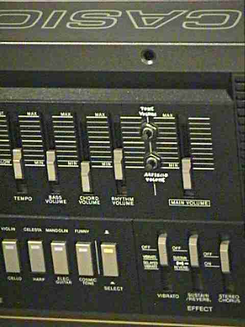
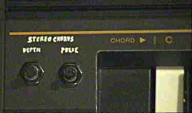
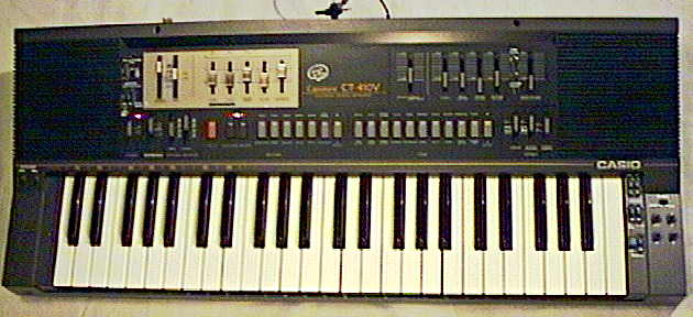
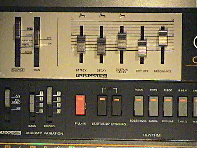
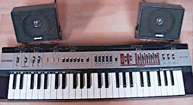
This keyboard from 1984(?) is definitely one of the most interesting Casio instruments, because it features a genuine analogue VCF (synthesizer filter) with filter envelope and cutoff/ resonance control sliders, lots of accompaniment variations and separate volume sliders. Additionally it has a wonderful "stereo chorus" rotary speaker/ leslie simulator that produces a great sort of "hemi- sync" mind machine effect with stepless adjustable speed, which makes the thing perfect for brain wave synchronization features in psychedelic meditation or tekkno trance music. A smaller version of this instrument with midsize keys and no built-in speakers was released as Casio MT-400V.
All sliders of this instrument are real analogue potentiometers and thus stepless. The stereo chorus LFO can also modulate the VCF in "wah wah" mode, which makes the typical "wokachika" sound known from certain 1970th funk musics. The great accompaniment unit has 4 bass and 4 chord variations and the same unique, dark and sonorously droning squarewave bass tones like the "organ" sound of the Hing-Hon EK-001. In fingered chord mode the accompaniment plays the more notes the more keys are pressed, and this works even perfectly with all non- chord key combinations, which permits very versatile accompaniment sound patterns. (This flexible behaviour is absolute no matter of course, see Yamaha PSS-390 for an annoyingly stubborn example.) And despite this instrument has already many built-in features, there are even still lots of additional keyboard matrix eastereggs to discover, which makes it perfect for circuit bending.
The semi-analogue percussion of the CT-410V sound rather unspectacular (no booming tekkno base or the like), but the decay time of all drums can be adjusted with trimmer potentiometers on the main PCB, and like all analogue drums they can be certainly modified in various ways.
The 20 main voices are fixed presets and not user- definable, but there are various mode switches (vibrato, sustain etc.) those modify them. The main voice generally sounds a bit dull when not sent through the VCF; this has partly to do with dull built-in speakers, but there is also a 1nF capacitor which unnecessarily muffles all timbres - throwing it out is strictly recommended and will improve the sound significantly. (In opposite to this my Casio MT-45 sounds very bright by default, despite it has the same accompaniment CPU.) The main voice sounds of the CT-410V consist of 2 mixed stair waveform tone suboscillators with different digital volume envelopes, those are (depending on the preset) muffled by 4 different filter capacitors. In the bass range many sounds turn into a more or less buzzy, sonorous purring drone, which is a characteristic style element of squarewave based instruments. These basses can resemble some of the famous POKEY sound effects on Atari XL homecomputers and are very different from the gradually duller and duller growing sine wave bass behaviour of average Yamaha FM keyboard sounds. When sustain is switched off, all sounds stop almost immediately after releasing the key, and the sound presets itself also contain neither vibrato nor tremolo.
Particularly the piano and the ringing "mandolin" timbres sound really dull, and also the too narrow pulse width of the mandolin makes it sound very unrealistic and buzzy at low notes. As usual with squarewave instruments, the dull "trumpet" sounds very artificial (but a much better trumpet timbre can be generated using the VCF). Most realistic sound the organ, flute and clarinet presets. The "funny" preset is a sort of rough digital slap bass (creaky picked e-bass) which sounds like "ennng!" (possibly it was initially intended to be called "funky", but sounded to artificial for this?). The "cosmic tone" preset sounds simply like a plain saxophone tone, thus I guess that its strange name was initially rather related to its 3 switchable envelope variants (those are normally not available on this instrument but can be added by an easy modification), because they turn it into a slowly duller fading spacey synth lead "meow" timbre, which makes audible use of the crossfading between the 2 subvoices. Both sounds belong to the brightest and most interesting ones of this instrument.
 Technically the CT-410V is completely mono, besides that the main
voice is optionally post- processed by the "stereo chorus" circuit, which
makes a pitch shifted version of it alternatingly pan left and right to
approximate a rotary speaker effect. Either the main voice ("tone") or
rhythm or bass + chord or a white noise source (chopped by the rhythm)
can be post- processed by the analogue low- pass VCF.
Technically the CT-410V is completely mono, besides that the main
voice is optionally post- processed by the "stereo chorus" circuit, which
makes a pitch shifted version of it alternatingly pan left and right to
approximate a rotary speaker effect. Either the main voice ("tone") or
rhythm or bass + chord or a white noise source (chopped by the rhythm)
can be post- processed by the analogue low- pass VCF.
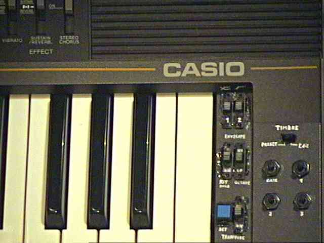
The VCF has sliders for cutoff, resonance and an envelope generator with sliders for attack, decay and sustain level. As usual, cutoff removes all frequencies above a certain value (i.e. muffles the sound or even mutes it completely when set very low), while resonance rises the frequencies near the cutoff value and this way a high resonance setting makes the timbre more hollow or metallic. The filter envelope modulates the cutoff value. In main voice ("tone") mode it is started by the begin of each new note (ignoring the key press duration), and because there is only one monophonic VCF, during polyphonic play the filter envelope affects all currently held down notes simultaneously, which permits an interesting gate effect because it can make held down notes fade dull or silent (by the filter envelope) and then sound again with full brightness during each new played note by the restarting filter envelope. Unlike this, when the VCF is assigned to "bass/ chord", its envelope does not restart with each new chord sound, but seems to ignore new bass/ chord notes so long its envelope is still in the attack or decay phase. Thus with fast rhythm tempo and slow envelope settings it makes rather a sort of "wokachika" sound (like known from 1970th funk(?) music and the oldest "Sesame Street" theme) instead of exactly following the chords. This way the accompaniment pattern gets differently stressed/ phrased by changing tempo or attack/ decay setting, which provides an interesting effect for tekkno. Instead of this envelope generator, the cutoff value can be alternatively modulated by the triangular wave LFO of the stereo chorus (no matter if the chorus effect is currently on or off) by selecting "wah wah", which makes a continuous filter sweep that can (depending on the cutoff slider setting) result in differently strong effects from mild tremolo to "wokachika" or chopping the sound. (Unlike a normal volume envelope, all these filter envelopes fade the sound not only quieter but also make it grew duller by reducing the trebles first.) Stereo chorus and VCF of this instrument have both a bit thin and slightly harsh sounding cheap op-amp chip timbre. In unmodified state the VCF permits no really high resonance level, and at full resonance the signal looses quite much bass intensity. Fortunately some simple circuit bending helps here to make it oscillate nicely and get half- way reasonable acid house sounds out of it.
There is also even a filter envelope input jack, which was originally
intended to plug in the Casio BFC-1 breathe filter controller -
a small black box with a mouthpiece, with that the filter cutoff value
should be controlled by blowing into it like playing a wind instrument.
(Likely this feature was intended as a competitive product to a similar
breathe input device of Yamaha's famous DX7 FM synthesizer,
which also had a special input jack for it.) Unfortunately neither rhythm
nor accompaniment are user programmable, and there is also neither a built-in
sequencer nor MIDI capabilities.
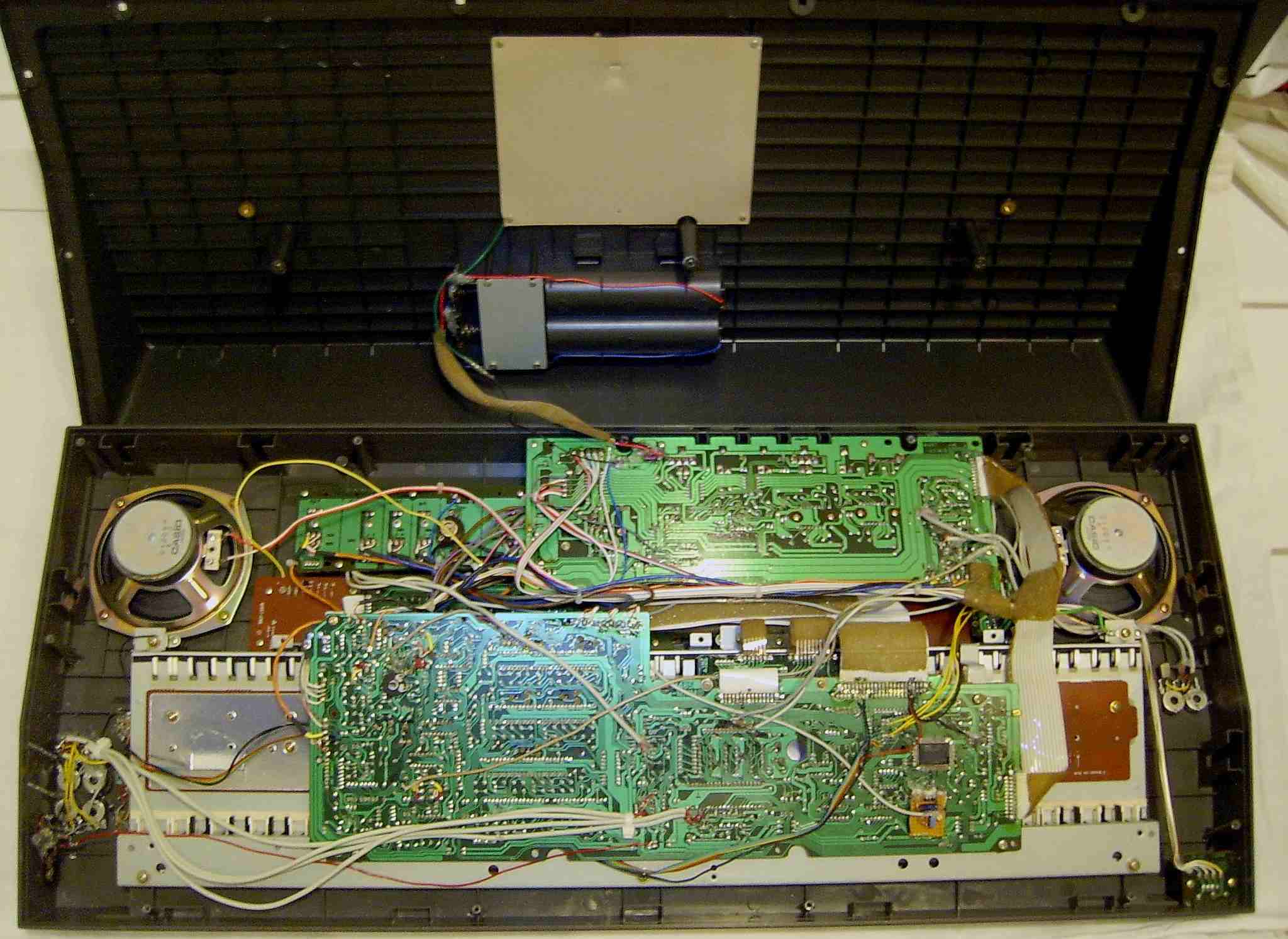
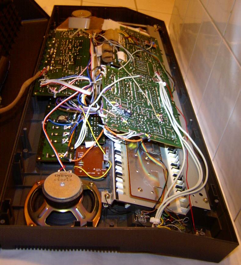
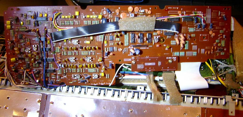
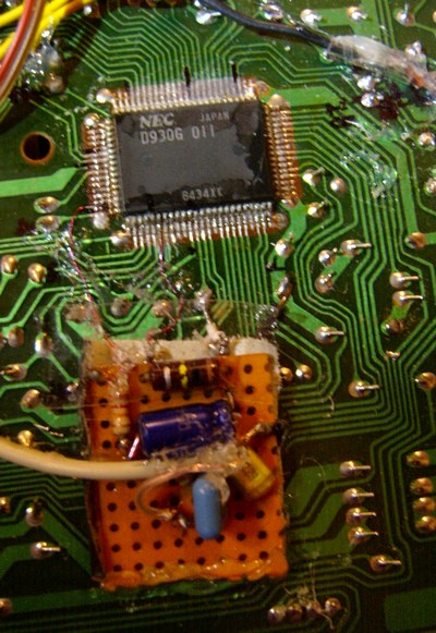
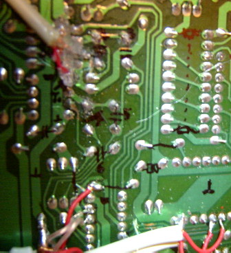
circuit bending detailsThis is a hardware analysis of Casio CT-410V (fullsize version of MT-410V), which is based on the MT-65 hardware class with an additional analogue VCF synth section. The Casio MT-65 is built around the accompaniment CPU "NEC D930G 011" and main voice sound IC "NEC D931C 011", so this text is valid for other keyboard based on these as well.
Most key matrix pins are at the top, and 2 at the left side of the D930G chip. The sound output and drum trigger lines are at the bottom side. Bass, arpeggio and percussion employ a capacitor decay envelope. important: All PCB locations in this text are viewed from the solder side with keys facing down. Regard that all PCB writings at capacitors only tell their capacitance; they are not part numbers and thus ambiguous. For correct APO (auto-power-off) control voltage, adjust trimmer VR1 until 5V is measured between left and right pin of the trimmer. See below how to disable APO. keyboard matrixThis matrix was initially analyzed by me, but later I filled gaps and fixed some bugs using Robin Whittle's essay and the Casio MT-65/ MT-100/ CT-405 service manual.
All unknown function names and in/ out numbers in this chart were chosen
by me. The input lines are active- low, i.e. react on GND, thus any functions
are triggered by a switch in series to a diode from one "in" to one "out"
pin.
CT-410V and MT-65 have a fixed diode at KI7->KC7, while the MT-45 has
at this location the "chord memory" switch and apparently the diode instead
at KI8->KC2. Thus in CT-410V or MT-65 solder a switch in series to the
diode KI7->KC7 and add a fixed diode at KI8->KC2.
 Despite
the soundchip does support sustain + reverb effect simultaneously, the
slide switch in the CT-410V only offers them separately. The switch
functions by a plastic handle with a leaf spring that presses down a conductive
plastic foil through openings in an insulator foil onto PCB trace contacts.
Thus I simply cut out the plastic bridge in the insulator foil between
"sustain" and "reverb." and bent the spring a little flatter down. This
way the switch will connect to both contacts simultaneously when switched
into an intermediate position. Unfortunately this caused note mess during
polyphonic play by shorting the key matrix lines KI5 with KI8 by the lack
of diodes in between. Therefore I placed a germanium diode into the line
from the switch's "reverb." output to fix this. (A silicon diode didn't
work here because there are already other diodes in series those caused
a too high voltage drop.) Despite
the soundchip does support sustain + reverb effect simultaneously, the
slide switch in the CT-410V only offers them separately. The switch
functions by a plastic handle with a leaf spring that presses down a conductive
plastic foil through openings in an insulator foil onto PCB trace contacts.
Thus I simply cut out the plastic bridge in the insulator foil between
"sustain" and "reverb." and bent the spring a little flatter down. This
way the switch will connect to both contacts simultaneously when switched
into an intermediate position. Unfortunately this caused note mess during
polyphonic play by shorting the key matrix lines KI5 with KI8 by the lack
of diodes in between. Therefore I placed a germanium diode into the line
from the switch's "reverb." output to fix this. (A silicon diode didn't
work here because there are already other diodes in series those caused
a too high voltage drop.)
My Casio MT-45 has arpeggio, and an MT-65/ MT-68 includes even 4 selectable variations of them. I really love this rhythmical chinking accompaniment effect, which IMO is one of the most typical and interesting style elements of classic electronic keyboards, thus it is a pity that with later Casio and Yamaha keyboards it was omitted because manufacturers apparently considered it out of fashion.
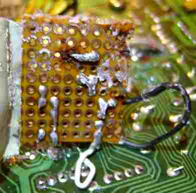
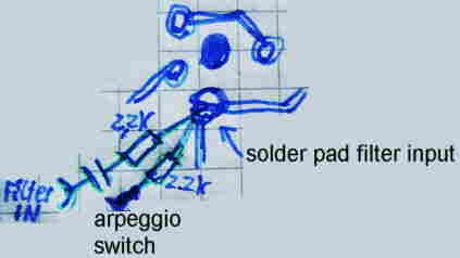
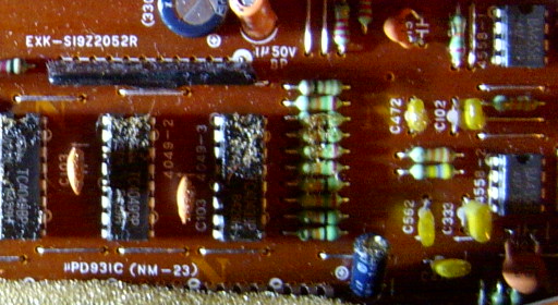
VCF and chorus input jacksTo send an external signal through VCF + chorus, connect a cinch jack through a 100nF cap in series to a 1 kOhm resistor with the rightmost pin of the hybrid module S19Z2052R, which is the resistor ladder DAC (25k/50k) for the main voice soundchip D931C. This modifies the external sound by everything that actually modifies the main voice (including its muffling capacitors).To send a signal only through the VCF (in any mode), connect a cinch jack through a 100nF cap in series to a 2.2 kOhm resistor with the strange looking divided solder pad below the VCF resonance preset trimmer pot at the left side of the main PCB. This solder pad is round and consists of 2 semi- circular halves with a small bridge in the middle; likely it was intended as a cuttable jumper for test purposes. The external signal this way will be sent always through the VCF, no matter if the VCF processes internal signals at the moment. (So far nothing is currently triggering the filter envelope, the "sustain level" and "cut off" controls must be set high enough to make the external signal audible.)
main voice volume controlParticularly when using the VCF, it is annoying that no independent volume control for the main voice exists. To add one, cut the trace from pin 1, 2 at the op- amp "4558-2" in the middle of the main PCB. Connect the the op-amp side with the right pin of a 22 kOhm log potentiometer, and its wiper output with the other trace end. Connect the left pin of the pot through a 10µF capacitor with GND. (This volume control works not when the main voice runs through the VCF - apparently the VCF gets the signal from another line that bypasses the timbre muffling capacitors.)
timbre change & distortionThe main voice sounds of the CT-410V consist of 2 mixed stair waveforms with different pulse patterns and different digital volume envelopes. (Also the reverb is technically only an envelope modification.) The waveforms are outputted through a hybrid module (resistor array DAC?) and are post- processed by 4 low pass filtering capacitors those are controlled through a "4066" analogue switch IC. These yellow plastic filter caps have the values {4.7nF, 33nF, 5.6nF, 470pF} (written on PCB as C472, C333, C562, C471) and are grouped together with a fixed 1nF (C102, makes sound dull) and 15pF (C15, ceramic) to the left of the NEC D931C sound IC close to a row of 10 resistors. The 4066 is DC controlled by 3 pins of the sound IC and can be also easily controlled by external switches to modify the timbres. (This timbre filter circuit is part of the main voice sound generator and has nothing to do with the additional cutoff/ resonance filter (VCF) of the CT-410V).I soldered a 4 channel alternating switch into the control lines to
the 4066 to make the 4066 inputs (pin 5, 6, 12,13) switchable between their
original soundchip outputs and 4 external controls. Instead of 4 simple
switches I connected here the wipers of 4 10 kOhm potentiometers to permit
analogue control over these inputs (use shielded cables against hum). The
4066 in this instrument switches its load fully "off" at voltages below
about 2.8V and fully "on" at about 2.87V, thus the pots need about 2.8V
at the left and 2.87V at the right end. To generate these voltages, I built
2 voltage dividers those each consist of [a chain made from a 330 Ohm resistor,
a 100 Ohm trimmer and a 220 Ohm resistor in series] from GND to +5V. The
trimmer wiper of the 1st voltage divider is connected with the "left" pins
of the 4 pots, and the trimmer wiper of the 2nd with the "right" pins.
The trimmers have to be adjusted until the potentiometers block all sounds
when fully turned left, and let it pass undistorted when turned a bit less
than fully right.
(The left values were old observations, the IO-# are taken from MT-65
service manual.)
note: When the main voice is routed through the VCF, these pots do nothing since the main voice apparently bypasses the normal timbre filter caps for this. remove dullnessIn comparison to a Casio MT-60 or MT-45, the CT-410V sounds quite dull. One reason for this are the big speakers with poor trebles, but the main reason is a totally useless and permanently active yellow 1nF capacitor (PCB text C102) near the switchable main voice filter caps in the middle of the main PCB. This annoying cap makes all sounds dull, which e.g. makes the characteristic harpsichord attack click almost inaudible. It is therefore strictly recommended to disconnect this muffler.
Unfortunately the label "C102" is ambiguous (only means "1nF") and PCB layouts may differ among versions. So for identification, temporary hold another slightly bigger capacitor (about 10nF) across its pins (wired parallel) while you play high notes. At the correct "C102" this will turn the main voice in all preset sounds (test this) even much duller and quieter, so you can safely remove it. extended tempo range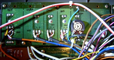 Unlike
with older Casios, the maximum rhythm tempo of the CT-410V is a
little slow. A 10nF capacitor at the right upper end of the main PCB controls
the tempo oscillator. Replace it with 4.7nF to speed up the tempo a lot.
(The still functioning minimum value may vary among instrument specimen,
since with a slightly smaller cap my CT-410V stopped the rhythm entirely.)
Due to this also rises the minimum tempo a little high, connect the open
end of the tempo potentiometer with a 680 kOhm resistor in series with
a trimmer pot (e.g. 300 kOhm) against GND. Adjust the trimmer in a way
that the rhythm barely stops (arpeggio can make a continuous tone here)
when the tempo pot is moved to minimum. This will provide you the maximum
possible tempo range. (With full tempo arpeggio sounds great.) Unlike
with older Casios, the maximum rhythm tempo of the CT-410V is a
little slow. A 10nF capacitor at the right upper end of the main PCB controls
the tempo oscillator. Replace it with 4.7nF to speed up the tempo a lot.
(The still functioning minimum value may vary among instrument specimen,
since with a slightly smaller cap my CT-410V stopped the rhythm entirely.)
Due to this also rises the minimum tempo a little high, connect the open
end of the tempo potentiometer with a 680 kOhm resistor in series with
a trimmer pot (e.g. 300 kOhm) against GND. Adjust the trimmer in a way
that the rhythm barely stops (arpeggio can make a continuous tone here)
when the tempo pot is moved to minimum. This will provide you the maximum
possible tempo range. (With full tempo arpeggio sounds great.)
VCF resonance improvement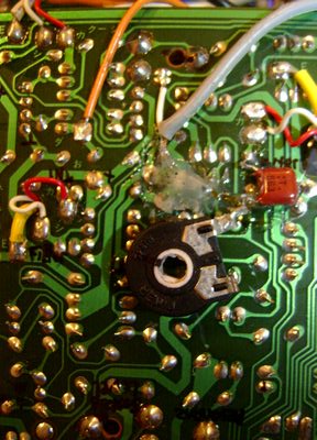 The
synthesizer filter of the CT-410V sounds a little boring because
it refuses high resonance values. Despite there is a resonance preset trimmer
at the left lower half of the main PCB, high settings of it eat much bass.
Even worse, instead of gently tweeting near the cutoff frequency, at high
resonance settings the VCF op-amp tends to run amok and suddenly squeak
without warning terribly loud (about 10 times of the rest) like a police
whistle at a far higher frequency than the cutoff value. To make the VCF
behave nicely, solder at the white wire of the grey shielded cable from
the resonance pot (upper left main PCB area) a 56nF capacitor in series
to a 5.2 kOhm trimmer pot (as adjustable resistor) against GND. By alternatingly
tweaking the resonance preset and the new trimmer, you can now adjust the
filter to friendly tweet around the cutoff frequency at low volume without
blasting away your ears. The VCF can this way even safely howl in self-
oscillation by its automatic envelope at maximum resonance and sustain
level without squeaking unbearable loud, and it will stop as soon sustain
level or the envelope drops below the necessary value. This permits also
nice "acid house" sound effects, although the timbre is a bit different
from a TB303. (Unfortunately there is no sequencer, thus you can only send
the accompaniment through the filter.) The
synthesizer filter of the CT-410V sounds a little boring because
it refuses high resonance values. Despite there is a resonance preset trimmer
at the left lower half of the main PCB, high settings of it eat much bass.
Even worse, instead of gently tweeting near the cutoff frequency, at high
resonance settings the VCF op-amp tends to run amok and suddenly squeak
without warning terribly loud (about 10 times of the rest) like a police
whistle at a far higher frequency than the cutoff value. To make the VCF
behave nicely, solder at the white wire of the grey shielded cable from
the resonance pot (upper left main PCB area) a 56nF capacitor in series
to a 5.2 kOhm trimmer pot (as adjustable resistor) against GND. By alternatingly
tweaking the resonance preset and the new trimmer, you can now adjust the
filter to friendly tweet around the cutoff frequency at low volume without
blasting away your ears. The VCF can this way even safely howl in self-
oscillation by its automatic envelope at maximum resonance and sustain
level without squeaking unbearable loud, and it will stop as soon sustain
level or the envelope drops below the necessary value. This permits also
nice "acid house" sound effects, although the timbre is a bit different
from a TB303. (Unfortunately there is no sequencer, thus you can only send
the accompaniment through the filter.)
Attention: Someone e-mailed me that this mod does not work with Casio MT-400V due to different hardware. I am not sure if both keyboards are indeed technically different or if there is even an error in my description. This is what he wrote: A couple of notes. On the 400v there's the resonance pot, right next to it is the cutoff pot. By tweaking these two it's possible to get the filter sounding pretty good. Also the wiring's different so I couldn't get the mod to work without having a drastic drop in volume on the filter output.The Casio MT-400V service manual claims they were identical. The following is (slightly shortened) the official VCF alignment procedure of the unmodified instrument.
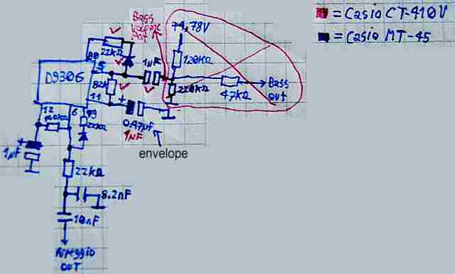
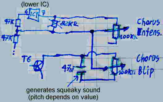
bass circuitThe bass output of the D930G employs a very similar envelope capacitor circuit like the arpeggio. It consists of an 1µF electrolytic capacitor (for decay duration) from pin 11 to GND and a 82 kOhm resistor from pin 11 to pin 5. There is a diode from pin 5 through a 22 kOhm resistor to pin 80. The sound is outputted through a 1µF electrolytic capacitor from pin 5.Interesting is that the Casio MT-45 produces a much softer, duller and more pressureful bass which timbre resembles a triangular wave or Roland TB303 (without resonance), while the CT-410V bass is a more sonorous droning squarewave tone. The MT-45 has instead of the 1µF envelope cap a 0.47µF one, and behind the 1µF output cap follows a 220 kOhm resistor against GND, a 120 kOhm resistor against +5V and a 47 kOhm resistor to the amplifier, but I doubt that this causes the difference. The CT-410V has after the 1µF output cap a black cable that leads to one input of the bass volume potentiometer, and its wiper (?) output is connected with a 22nF muffling cap against GND (located 3cm below the bass volume pot cable near the corner at the top of the middle of the main PCB) and resistors lead the signal to the amplifier. Bridging the muffling cap with a bigger one makes the bass indeed duller, but in spite of this it won't really sound as smooth and pressureful as the MT-45; a too big additional cap here only reduces the bass volume too much. I guess that the MT-45 circuitry has a much higher inner resistance and thus doesn't damp the bass as much as the bass volume pot stuff of the CT-410V does. (When I experimented with adding the bass potentiometer to the Testron I discovered similar behaviour.) Increasing the envelope cap value makes the bass decay slower (and thus sound less dry), but this also doesn't imitate the MT-45 bass sound. (The MT-45 has even a smaller instead of a larger cap, but this is likely rather caused by the higher inner resistance of the rest of its circuit, because it doesn't seem to fade the bass silent much faster. Certainly potentiometers can be added here to make the envelope and muffling capacitor values adjustable etc., but I didn't modify this.) Possibly the CT-410V has even intentionally a less dull bass with more overtones to sound stronger when processed by the VCF. Which bass sounds "better" is a matter of situation or personal taste and there is no objective answer for this. stereo chorus modificationThe stereo chorus is a separate unit that can post- process the main voice. It was intended to approximates a rotary speaker effect by panning a pitch shifted version of the signal left and right, that is mixed with the original signal, but in fact it resembles much rather the hemi- sync signal of a mind machine, and thus can be greatly used for meditation music, because the chorus speed is stepless adjustable by a slider. The stereo chorus circuit is located at the right side of the amplifier PCB; it contains 3 small ICs (each 8 pins, from top to bottom: MN3209 (BBD), MN3102 (clock), BA4558 (op-amp)) and various discrete stuff with 2 transistors.In CZ-5000 service manual I found hints how the high-end version of a Casio stereo chorus works. In that circuit the mono audio signal first goes through a low-pass filter to remove components above 20KHz and then through a compressor, that amplifies small signals to reduce noise (similar like Dolby B). Then it is routed parallel through 3 lines (left, right, center), each made from a 256 stage bucket brigade device (MN3209) and an expander (to undo the compression). 2 three phase LFOs (0.54Hz and 6.1Hz) produce 3 out-of-phase control voltages those each wobble the clock frequency VCO of a bucket brigade device (between 33.3 and 55.6kHz) to vary its delay time, which produces the rotary speaker effect. At the end the center channel is partly mixed into the left and right channel audio by resistors. This kind of 3 line stereo chorus also exists in Casio CT-6000 (seen in service manual); the 0.66Hz triangular wave of its panning LFO additionally can be modulated with a 2nd faster triangular wave (8.33Hz) to produce the "ensemble" effect. A bucket brigade device delays a signal by passing it through a chain of analogue RAM cells with a certain clock rate. It can be imagined as a crude sampler that records and playbacks simultaneously and so mimics the behaviour of a tape echo. So the effect is basically like modulating the tape speed of 3 tape echoes out of phase, shifting their pitch up and down. However in CT-410V the stereo chorus circuit is much simpler, using only one MN3209 line without compressor and expander stuff. I expect that as stereo channels it simply forms the sum and difference between the MN3209 input and output signal.
semi-analogue percussionThe percussion sounds are semi-analogue. Hiss sounds (cymbal, hihat, snare) are digital, but their decay envelope and all the drums and claves are analogue, made from discrete circuitry (no hybrid modules) with each a trimmer for decay time adjustment, thus they certainly can be modified in a lot of ways. Because they are triggered by pulses at individual output lines of the D930G, it would be certainly possible to modify the preset rhythms a lot (I haven't done this) by muting individual drums or even connecting them through a switch matrix in different orders, similar like the "Super Drums" rhythm variation slide switches in other Casios. (I first thought the MT-52 would be wired this way, but it does the switching in software.) The white noise is made from 2 mixed digital shift register feedback noises of the D930G, those get filtered by the analogue envelope hardware. This percussion type sounds a bit thicker than Casio's older fully analogue percussion (e.g. in MT-70). Both types can be easily distinguished by turning the instrument's tuning trimmer; if percussion changes pitch with the main voice (here only hiss timbres) then its oscillators are digital.Different Casio keyboards with the same D930G can contain different percussion; my MT-45 has e.g. 2 drums (congas) less than the CT-410V. This is what Casio considers the official decay settings (fall time
down to 10% of initial level, found in MT-65 service manual).
In that manual each "normal" drum and 'claves' employs only 1 transistor to produce a decaying sine wave (CR oscillation circuit). 'Hihat' and 'cymbal' each employ 2 transistors and the white noise output from D930G. Most complex is the 'snare', which mixes the outputs of 2 circuits (each 1 transistor) for drum and said hiss component. The trimmer names seem to differ among models; CT-410V does not match the MT-65 description. The MT-400V service manual does not even mention them. pitchbendThis instrument has already a built-in tuning potentiometer, thus here certainly easily one or more pitchbend pots could be added. (I didn't add one yet.) But be warned that the clock oscillator is AC controlled, thus do not connect simple sensor contacts here, because they would flood your nervous system with maladjusting and potentially cancer causing high frequency crap.shitshotBy re- plugging the power supply plug, the main voice sound envelopes change a lot. Most of these shitshot sounds distort much during polyphonic play. While sustain and vibrato behaves as usual, the operation of the added "envelope" switches always reset to a default sound. Also selecting another preset sound clears these sounds (as expected), thus I conclude that much like with Yamaha FM keyboards, the D931C soundchip is programmed with synthesis parameters a single time by the main CPU D930G when a sound is selected, and it keeps these parameters in internal registers until a new sound or envelope is selected (or a shitshot messes them up).pinout D930GThe Accompaniment LSI "NEC D930G xxx" (80 pin SMD, pins count anticlockwise, xxx = software number of internal ROM) is one of the most interesting squarewave accompaniment CPUs ever made by Casio, because although it features only 12 rhythms, it has for each of them 4 chord, 4 bass and 4 arpeggio variants and features wonderful dark and sonorously droning multipulse squarewave bass and chord tones with different pulse patterns. It is 6 note polyphonic (4 chord channels, bass, arpeggio), and all tones have separate output lines (those partly need external envelope capacitors). It features also separate outputs for 7 analogue percussion trigger pulses and a static percussion waveform (2 mixed shift register feedback noises) for snare and hihats. Drums and clave timbre are made from external analogue circuits. The switchable multi-track accompaniment is detailedly described in the US patent 4624170. The D930G also acts as keyboard matrix decoder for keys, control switches and accompaniment section keys. It contains in its ROM also definitions for main voice preset sounds those it can output through a 4-bit bus to the external main voice sound IC D931C (e.g. in CT-410V); in other instruments (e.g. Casio MT-45) this feature is not used. The keyboard matrix outputs are multiplexed as address bus out in keyboards with additional rom, ram or percussion IC (seen in MT-500 service manual). The data bus is only 4-bit.The "D930G 011" can also be controlled by an external CPU (e.g. D7801G
used in Casiotone
7000 or the Symphonytron
8000 accompaniment unit RC-1
- both control also D931C from there instead of connecting it with D930G).
D930G xxx versions with other software numbers differ in accompaniments,
preset sounds and have additional features (e.g. supporting percussion
ICs) those typically reduce the count of accompaniment variations (likely
due to limited internal ROM space).
This pinout was based on the service manuals of Casio CT-405/MT-65/MT-68/MT-100, CT-430, CT-620, MT-52, MT-500 and MT-800. Apparently all "O-#" pins are outputs, "I-#" are inputs. "DB-#" are data bus. The naming convention in service manuals is ambiguous, so in many places "O-#" is named "O#", and even "KC#" pins in some places are refered as "O#" with same number. In later schematics the "-" was omitted. Software number 019 behaves almost exactly like 011 (same keyboard matrix layout), but controls a percussion IC and has some changed preset sounds. The Technical Guide For Casiotone from 1986 mentions software
number 018 also for MT-800 (mine has 017) thus it may be a bugfix
release.
Many unused pins of D930G version "011" (e.g. data bus) have a meaning in other software numbers. E.g. MT-800 ("017") supports a ROM-Pack slot and MT-500 ("022") a sample percussion IC; both also have additional RAM. In MT-800 many things get demuxed from address lines by latches clocked by pins 77..80. In MT-500 4 drumpads are buffered in a latch that is clocked by pin 26 to output its 4 signals to the data bus (pin 65..68). According to its service manual, a 4-input NOR triggers an interrupt at pin 42 when multiple (or any?) drumpads are hit. Pin 73 selects the active nibble of the 8 bit percussion ROM to be read through the 4-bit data bus. In MT-210 its early percussion IC is controlled through pins KC#, 18, 64 but no data bus. The CT-7000 has no sound IC wired to its D930G because it feeds its 2x D931C directly from an additional CPU that controls the D930G apparently by simulating key presses. In CT-7000 the undocumented pin 31 is wired through an 1k resistor to pin 33 (+5V), so it may inform the D930G about the absent sound IC or even change the data format for being controlled by an external CPU. This looks like a model select feature. The 1k resistor hints that pin 31 can also act as output. The same is done in RC-1 (Symphonytron accompaniment unit), which pin 33 is even wired through a 100 ohm resistor to +5V and so may get influenced if pin 31 can pull lo. Apparently a direct predecessor of this hardware class was the accompaniment CPU D910G with main voice sound IC D990G, those were used in Casio MT-60. pinout D931CThe Melody LSI "NEC D931C" (42 pin DIL) is an 8 note polyphonic sound IC with digital envelope (4 steps, including vibrato, mandolin ring), that was used in many Casio keyboards in mid of 1980th. It supports 17 bit digital audio output (pin O1..O17) of that however in Casio keyboards only 14 bits were actually used (wired to external resistor ladder DAC). Most unusual is the very high mixing frequency of about 600 kHz, which prevents the infamous DAC aliasing noise known from other (especially more modern) home keyboards. Each sound is made from 2 layered subvoices with independent volume envelope (what Casio called "Consonant-Vowel-Synthesis"). These envelopes have each 4 linear sections {attack, decay, release 1, release 2} (each 3 bits). They stay in sync with each other and can not be selected independently; 3 bits select 8 envelope type combinations. The release 2 (when not disabled) starts when release 1 reaches 1/2 or 1/4 of peak volume, and reaching 1/8 it starts to decay slightly slower or much slower with active 1.7s reverb, which is suitable to approximate exponential decay of acoustic instruments. While the timbres strongly resemble multipulse squarewave, the waveforms are not strictly square, but according to Robin Whittle each suboscillator uses 16 stair steps where each step height is switched by volume increments of +/- {0, 1, 2, 4, 8}. The waveform height is up to 6 bit (+/-31, only 5 bit should be used to avoid overflow by the 2nd waveform) which is multiplied with the 8 bit volume envelope. The resulting 14 bit (2 added suboscillators) from all 8 polyphony channels are finally summed as 17 bit digital audio. There are mode bits to flip, mirror or repeat the waveform for more timbre variations. Particularly important is that the generator can skip either the positive or negative halves or even pass only every n-th wave cycle (i.e. inserting after each wave cycle 1 or 3 wave lengths of silence or after every 2 wave cycles 2 wave lengths of silence) which creates the famous buzzy bass range known from squarewave based instruments.Additionally it can select (in CT-410V and others) 8 timbres through an external analogue filter circuit with 3 digital switch inputs. (The maximum possible number is unknown, but there seem to be up to 7 CPU controllable IO pins while the filters are actually set as a 4 bit value which suggests 4 lines for up to 16 timbres.) In MT-800 IO-4 mutes sound as click noise prevention while filters are switched. Beside filter, the sound engine seems to be multitimbrale. As a pure sound IC the D931C contains no preset sound definitions. Only envelope durations are mostly predefined and so can be switched only through few bits. E.g. the mandolin ring is hardsynced to a fixed 12.7Hz LFO of the vibrato circuit and gets retriggered only after envelope has finished section 1 and 2. Also tone scale and octaves are predefined, while transpose is handled by the main CPU. During keyboard play the CPU only sends note-on and -off codes to the sound IC. So it is unknown what later ROM revisions were supposed to do (none are known); perhaps they should permit additional increment widths (as the partly redundant 4 bit resolution value suggests - the 2^n limitation was apparently chosen to permit fast multiplication by bit shifting - see below) for finer waveform definition. The pinout is really a mess, which suggests that it may be based on a generic microcontroller running a special software in its internal ROM, but the high mixing frequency makes this unlikely. The IC is often labelled "NEC D931C 011", which suggests that 011 is the software number of internal ROM, but no other versions have been found, so it may have been named after the matching "NEC D930G 011" CPU it first got paired with. This pinout and description is based on Casio DG-10/ DG-20
schematics (doesn't tell functions), service manuals of MT-65, MT-800 etc.
and Robin Whittle's detailed
analysis Casio-931-2006-06-17.txt in which he identified the data
format to control the D931C in software. Apparently all "O#" pins are outputs,
"I#" are inputs and "IO#" can be both. "DB#" are data bus. The pin naming
convention is ambiguous; the service manuals in many places insert or omit
a "-" before the # number.
The 'clock master /slave' input is wired to VDD to generate its own clock. According to Whittle's description it should be pin 12, but in the DG-20 schematics and my own CT-410V it is pin 11. After audio bits change, pin 23 goes hi to trigger an external sample & hold circuit (according to service manuals in MT-52 and MT-500 only 25kHz) for a better DAC, which fails because bits have not stabilized yet when the pulse arrives. The 4 bit data bus is completely asynchronous (handshake controlled through 2 strobe lines) which makes it independent from the main CPU clock (which e.g. may be synced to midi or a display) and so permits analogue pitch control (tuning, pitch bend) through clock speed. The bus protocol has a simple infix structure that transmits triplets of 4 bit address, 4 bit data and 4 bit subaddress while 2 strobe lines indicate which nibble is currently sent. Interesting is that the serial data protocol defines envelopes by feeding a bit sequence (26 nibbles using only bit 1 and 4) through a long shift register chain, which to me (I am no expert) strongly resembles JTAG. The apparent reason for this is that the sound generation for the 8 polyphony channels is time multiplexed (summed at the end as a 17 bit DAC output value), so all register contents of the sound IC is anyway stored in circular multi-bit shift registers (see patent below), because for fast hardware multitasking, after processing each channel they cycle to the next entry. It would be interesting to program a modern microcontroller with matrix LCD as a graphical sound editor with step sequencer and midi to control this sound IC. Robin Whittle explained in his great bulletin "Modifying the Casiotone Instruments" from 1981 about the MT-65 hardware family (which he calls "Series V"): "... these are really worth getting excited about! The sounds are brilliant by any standards - better in my opinion than the Series I [Casiotone 201 etc.] and the sound LSI puts out 16 [genuinely 17] bits, only 14 of which are normally converted. I have made a good 16 bit anti-glitch DAC and can tell you that the results are stunning. [...]Robin Whittle explains in "Casio-931-2006-06-17.txt" that in the lengthy setup protocoll the same sound definition parameters need to be transmitted 8 times for shifting them serially into the memory of each of the 8 polyphony channels. What he considered a chip layout simplification, to me clearly indicates that the D931C was designed for supporting multitimbrality, because note-on/off data sent by the CPU selects individual channels, so the CPU always knows which channel is used and so during setup can decide which sound parameters it shall have for which notes. Only the DAC exists only once, which limits that all channels will need to use the same analogue filter setting. Major parts of the D931C sound engine are disclosed in US patent 4590838 (with Japanese priority dates from 1978). However this does not describe a finished sound IC, but the circuitry of an obviously incomplete self-contained instrument prototype with 48 keys and layering capability ("multi-performance mode") in the manner of US patent 4387619 (see Casiotone 201). Unfortunately patent 4590838 is even more cryptic than the latter because the schematics even use proprietary miniaturized logic gate symbols to save space, and instead of using ROM, all preset sound parameters (like waveform and envelope) are vaguely referred as a bunch of "switches". (Particularly in "multi-performance mode" real switches would make no sense at all, because they permit no multiplexed selection of different sounds for each channel.) It even patents a unique synthesis mechanism that seems to be absent in the actual D931C. In patent 4590838 the sound generation for the 8 polyphony channels is time multiplexed, thus like in most 1980th Casio keyboards, all register contents of the sound and envelope hardware is genuinely stored in 8 stage circular multi-bit shift registers. As a form of hardware multitasking, after processing each channel they cycle to the next entry every clock step. The waveform is defined by increments. Any waveform has up to 256 clock steps (depending on pitch) divided into 16 blocks; each block is rectangular (like a stair step of a sample) and defined by a 3 bit increment ("differential coefficient" +/-{0,1,2,4}). Another bit selects which of 2 simultaneous envelopes {alpha, beta} shall affect it. Only block 0 stays always zero with fixed 10 step length (possibly due to unstable data during fetch cycle). Thus a waveform definition takes 4x 15 bit. As expected, a volume envelope is multiplied with the waveform, but the implementation is really bizarre. The "waveform program designation section" (here obfuscated as a strange bunch of switches) outputs the differential coefficient of the actual block to an integer multiplier, that multiplies it with the output of the volume envelope counter that is stepped with the "control amount" for envelope steepness T. Like the differential coefficient, also the control amount (+/-{0, 1, 2, 4, 8, 32}) is always a power of 2. The reason for this is that this simplifies the multiplier implementation into a small gate network (only 34 gates) for hardwired bit shifting, that works within a single clock step and also forms complements for subtraction. (A general purpose multiplier would need to deal with carry and need many clock steps or a huge lookup table.) The envelope counter has 32 steps ("envelope coefficients" 0..31) and is wired through the "synchronizing set register" to step only during block 0 (to avoid glitches?). The result is summed by an adder + accumulator and (after the pitch correcting stage) finally output through a 13 bit DAC. The envelope register has 7 bit; 5 bits indicate the 32 envelope steps, 2 upper bits the envelope state {clear, attack, decay, release}. Some envelope shapes use the additional internal signals "high release" (rapid damping, truncates to zero when decay reaches 8) and "slow release". The envelopes are defined by these parameters ("switches"): Decay clock DA (1 bit), DB (3 modes), Release clock RA (1 bit), RB (4 modes), RC (3 modes for slow release), organ envelope OA (1 bit), vibrato clock SA (1 bit), SB (1 bit). Aa, Da each select envelope addition value {1, 2, 4, 8, 32} for attack, decay, release, slow release, high release. T1 = tremolo flat, T2 = touch tremolo (only when key held and T1 is off), T3, T4, T5 control tremolo depth {1, 1/2, 1/4}, T6 enables mandolin ring. All T# parameters are implemented by gates affecting the envelope counter. The tremolo loops potions of the decay and release phase. Switch B enables vibrato. While this ADR envelope generator itself is only linear and not that unusual, the really crazy part comes now, that is to say, there are 2 envelopes running simultaneously, and unlike normal synths, in the prototype these don't control different oscillators, but different sections in the same waveform. I.e. each of the 15 blocks (set by its beta bit) can be multiplied either by the alpha or the beta envelope to produce lots of freakish timbre changes. So the 1 bit parameters ("switches") S1, S3, S5 enable the attack, decay, release sections of the of alpha volume curve. S2, S4, S6 do the same for the beta volume curve. S10, S11, S12 (3 bits) indicate alpha and beta period modes to produce undertones (and buzzy bass range) by skipping every nth waveform cycle (set it 0) in alpha or beta {(1, 1), (1/2, 1/2), (1/4, 1/4), (1, 1/2), (1, 1/4), (1/2, 1/4), (1/2, 1/3), (1/3, 1/3 OR 1/2)}. The "1/3" mode is implemented by making the 8 step cycle counter skip steps 4 and 5. Parameter R1 inverts alpha/beta designation signal (beta bits from waveform definition). R2 is non-separation indication only with duet performance (2 layered sounds). R3 inverts all relation of alpha and beta (for each block). Depending on settings, either alpha and beta affect all lines memory (polyphony channels), or alternatingly alpha for even and beta for odd cycles. In older Casio patents note pitches are produced by frequency dividers and binary counters. To correct the pitch of some notes, gate logics make counters stop at certain clock cycles. But here pitch correction works differently. The output is written into a kind of ring buffer ("shift memory") that holds the actual increment (10 bits) of the 8 polyphony channels, but unlike the known Casio 8 stage shift registers for polyphony multitasking, this one has additionally 3 address lines to write directly into different cells than the active polyphony channel (controlled by gate logics depending on selected note and octave) and so delay the signal differently for each of the 16 block in a waveform to correct pitch. While block 0 always has 10 steps, the period duration of others depend on note pitch and varies by 1 during the other 15 steps (e.g. in highest octave the high C stays 8, but the low C toggles between 15 and 16). One basic clock step (here 272510Hz) is one step of the sound wave. Each of the 16 block of a waveform cycle has to be >=8 basic clock steps therefore each "clock" (block?) address has >=8 steps. The highest note pitch has 130 clock steps. (Ring buffers are commonly used for jitter compensation and delay adjustment in software based sound synthesis, so it is a bit surprising to find one here. The idea is to put values at varying positions onto a running conveyor belt (or moving a tape head during recording) and so stretching and squashing the output.) But this reference implementation strongly differs from the actual D931C. As a self-contained keyboard instrument, an 48 stage shift register (one bit per key) memorizes which keys are already held, so only changes during key scan are sensed as note-on and note-off commands. The multi-performance mode layers polyphony channels by writing data to 2, 4 or 8 tone generators per key press (parameters W1=no, W2=duet, W3=quartet, W4=octet). A special flipflop holds notes for minimum 45ms. Interesting is that in this implementation the note pitch value of a released key is used to identify to which polyphony channel a note-off command should be sent. This may be the reason why with trilled notes older Casios occupied multiple polyphony channels (making nice volume increase and phasing) while newers don't. There are no analogue filters shown behind the DAC, but the patent claims mention that they may be added and that e.g. instead of switches, waveforms may be stored in ROM or magnetic cards, and that all those infamous 8 stage shift registers (of course) may be replaced by conventional RAM. It says that a note may be also made from layering different preset sounds or from layering the same waveform with small pitch difference (for chorus effect). However it does nowhere suggest implementation as a sound IC controlled by an external CPU.Compared with this, the actual D931C has many details changed. Most important is that it (unfortunately) does not synthesize timbres by making 2 envelopes affect individual sections within the same waveform, but instead simply layers 2 waveforms those have each a 4 step linear volume envelope with reverb simulation. Both envelopes can not be selected independently but have 8 fixed combinations. Different linear release times approximate natural exponential behaviour. 2 additional bits can speed up the envelope and vibrato clock. The waveform is made from 16 equal blocks (0 isn't special here) of increments +/-{0,1,2,4,8}. Vibrato = {off, narrow, wide, delayed wide}. Sustain = {off (0.25ms), sustain 0.9s, long sustain 1.2s + reverb tail, reverb 1.7s, sustain 0.9s + reverb 1.7s}. The reverb tail lasts another 1.5s after volume decays to 1/8. There is no tremolo. Waveforms can be flipped or mirrored. The highest octave setting can use a mode that sounds only every 2nd, 4th or 8th cycle. About the data format also see below. For further technical details read Robin Whittle's analysis. He mentions various unidentified parameters in the D931C; it would be fascinating to figure out if the mysterious block envelope synthesis perhaps still slumbers unused inside as an easteregg. The patent text claimed about it: "Thus by indicating two volume curves of alpha and beta, the system can simultaneously indicate waveforms alpha and beta. Therefore when waveforms are different, rises and falls of the volume curves may be changed so that a proper combination of them provides a great variety of a musical sound waveform synthesized. Accordingly, the time-variation of a harmonic structure of the waveform is remarkable to produce a musical sound wave with rich timbre. Accordingly, the musical instrument thus constructed according to the invention can produce a musical sound with features peculiar to the sound produced particularly by brasses and strings..."I would love to know what that brass had sounded like; the "trumpet" of CT-410V definitely sucks. Likely direct successor of the IC D931C was the Music LSI "NEC D932G" (64 pin zigzag DIL) that was used only in Casio CT-6000 and CPS-201. It communicates with the CPU through 8 input and 4 output pins, has 17 bit audio and additional 14 control output pins for external filters, mixing ratio, stereo chorus and the like. The velocity sensitive highend midi keyboard contains 3 of these unique sound ICs; each is wired to an own DAC with different fixed analogue filter (each 3 control lines). The outputs are mixed; in chord mode the 3rd sound IC is used for chord only, else all 3 are layered as main voice. I suspect that in classic Consonant-Vowel manner the mixing ratio between multiple differently filtered sound ICs changes with keyboard velocity. The existence of so many switchable filters seems to disprove the rumour that CT-6000 was a secret unofficial first phase distortion instrument. The high timbre quality rather results of 17 bit DAC resolution and complex analogue post-processing through filters and a costly 3 line stereo chorus. Even its unique percussion generator IC HD61701 (54 pin SMD) routes some outputs through 2 external filters to shape timbres.
This is the different keyboard matrix of Casio CT-620
from 1986, which is an 61 keys variant of MT-65 hardware with CPU "NEC
D930G-013".
I neither own nor intend to buy this large keyboard, but here it is for
completion. The earlier Casiotone 610 (CPU unknown) looks very similar.
This layout is based on CT-620 service manual & schematics, so there
are likely unknown eastereggs (possibly the whole MT-65).
|
|
|
|
|
|
|
|
|
|
|
|
|
|
|
|
|
|
|
|
|
|
|
|
C1 |
C#1 |
D1 |
D#1 |
E1 |
F1 |
|
|
|
|
|
F#1 |
G1 |
G#1 |
A1 |
A#1 |
B1 |
|
|
|
|
|
C2 |
C#2 |
D2 |
D#2 |
E2 |
F2 |
casio |
fingered |
|
|
|
F#2 |
G2 |
G#2 |
A2 |
A#2 |
B2 |
off |
accomp select |
|
|
|
C3 |
C#3 |
D3 |
D#3 |
E3 |
F3 |
arpeggio |
accomp variation |
|
|
|
F#3 |
G3 |
G#3 |
A3 |
A#3 |
B3 |
sustain |
|
|
|
|
C4 |
C#4 |
D4 |
D#4 |
E4 |
F4 |
|
synchro |
|
|
|
F#4 |
G4 |
G#4 |
A4 |
A#4 |
B4 |
start/stop |
fill-in |
|
|
|
C5 |
C#5 |
D5 |
D#5 |
E5 |
F5 |
|
|
|
|
|
F#5 |
G5 |
G#5 |
A5 |
A#5 |
B5 |
|
|
|
|
|
C6 |
rock |
pops |
disco |
16 beat |
swing |
latin swing |
|
|
|
|
pipe organ |
piano |
harpsichord |
flute |
clarinet |
select |
|
|
|
|
|
trumpet |
violin |
accordion |
synth. guitar |
funny |
select |
|
|
|
|
All unknown function names and in/ out numbers in this chart were chosen
by me. The input lines are active- low, i.e. react on GND, thus any functions
are triggered by a switch in series to a diode from one "in" to one "out"
pin.
legend: |
|
|
|
= keyboard key |
|
|
= function needs locking switch (i.e. stays active only so long the switch is closed) |
|
|
= rhythm |
|
|
= chord |
|
|
= orchestra (main voice sound) |
Especially after these modifications, the CT-410V constitutes a respectable sounding analogue synthesizer that can do many similar effects like known from early Jean Michael Jarre works; with the arpeggio mixed into the main voice and routed through the VCF, you can e.g. get the typical style of chinking atmospheric melody clouds known from these records. Unfortunately nothing is programmable, which limits the instrument to its standard rhythms and accompaniments, although they permit many variations. (Without any sequencer you also soon wish a 2nd pair of hands to crank at the knobs while playing on it, but early Moog synthesizers also had none anyway, and Jarre played live in spite of this. ;-) )
I read in a forum that when Casio
developed their first soundchips, they were urged to transmit their digital
waveform data between CPU and soundchip in an odd format based on incremental
values to prevent conflicts with a digital pipe organ patent by the church
organ manufacturer Allen, who had introduced the banal concept of
adding a digital envelope to digital waveform samples. I am not sure if
the simple squarewave sound of the D931C is really affected by this, but
the shitshot distortion may have to do with improper increment sums those
cause a DC offset on the output waveform that exceeds the DAC range. The
forum article was written by Robin Whittle and I have included it here
for educational purpose because it mentions the D931C chip and may help
to bring more light into the sound synthesis technology of historical Casio
keyboards:
Re: [music-dsp] patents (the softsynth was patented 1997)To: music-dsp from shoko calarts edu
He assured me that Allen had licensed a patent, by one Ralph Deutsch (if I remember correctly, and I haven't thought of it for 18 years or so) which was for a musical instrument which worked by storing a digital representation of a waveform in its memory. He showed me the patents - I may still have copies somewhere. He was intrigued by the Casios - the first production digital keyboards. He was convinced they used a curious form of synthesis, the name of Walsh Functions - some mathematical abstraction of little obvious importance - because he was sure that Casio would not want to be caught out on Allen's worldwide patents. The Casio M10 chip and its siblings in the MT-30, MT31, CT-201 (the very first Casio - 4 octaves, full size, two chips with different waveforms) work by generating complex 16 step waves (I assume this from what I know about a later chip I describe below), eight notes at a time. The waves are made of two component waveforms and there is crude envelope control over each. The sum of the 8 waves appears as a 14 bit binary number at a sampling rate of about 500 kHz. This means nice, crisp, non-aliased high tones! The DAC was inverters driving a R-2R resistor array for 12 bits and a few resistors for the least significant 2 bits. There was no sample and hold - just an op-amp - so timing anomalies in the bits from the chip and the inverter slew rates caused spikes when the wave went from 10000x to 01111x. The waveforms were pretty crude and of course made of stair-steps. The signal went through a switchable analogue LPF - but my mods bypass that. I even made a super-low glitch tweaked dual 14 bit DAC mod board for the CT-202, using the standard Casio R-2R network and some extra resistors, trimpots and judiciously clocked HC174 latches so the rising and falling edges were symmetrical. Later, in 1982, Casio produced a similar sounding MT-65 and its full-size equivalent. The sound chip in this is a 42 pin custom LSI which has its note playing and waveforms loaded into it by an external CPU and software. Around then, I figured out the protocol for talking to the chip and wrote a C program (BDS-C for Z80 CPM) to write waveform data to the chip via the parallel port of a Big Board I. The reason I mention the Casio is that the chip (the NEC D931) did not actually receive, or apparently store, waveforms. It received and stored *increments* - and used these steps to generate the waveform. If your increments did not add up to 0 then all sorts of trouble occurred! Let me look into my archives . . In less than a minute I found the patent! US Patent Office 2 June 1970 Patent 3,515,792There is no mention in the prior art of computer software generation of music - though I guess no-one had used a computer to make an *organ*. Using increments (albeit simple +/- 1, +/- 2 +/- 4 +/- 8) was probably harder than simply storing the waveform, and led to less flexibility than a stored waveform - but I figure that Casio did it so they didn't have to worry about the Allen patent. So the dull force of patent law made a popular instrument more awkward, or at least more idiosyncratic. I just found my doco file for the chip in the MT-65 - the D931. All the guff is there on how to talk to it. I have C-code as well - and 8 D931 chips, seven unused. I was able to load novel waveforms into the D931 in my MT-65 it and then play it from the MT-65's CPU via its keyboard, or the MIDI interface I added. I also made up a second D931 on an external board with an independent clock source so I could have two waveforms and detuning. A web search for: "Ralph Deutsch" and patentleads to: http://www.allenorgan.com/book/jbook.htmwhere there are two blank pages, entitled: Honoring the Intellectual Property of Othersamongst a lot of other similarly empty pages referring to patent litigation. The author is Allen Organ founder Jerome Markowitz, who died in 1991. He had been dabbling in electronic organ patents since the 1930s. I have some patents of his here, from 1973, on internal plumbing inside digital organs. - Robin dupswapdrop -- the music-dsp mailing list and website: subscription
info, FAQ, source code archive, list archive, book reviews, dsp links
|
I had downloaded a sound demo record of the Casiotone 202, which was the direct successor of the Casiotone 201, but the 202 there seemed to have far more natural sounding timbres than my CT-410V (D930G/ D931C chip set like MT-65). But now I think this was likely rather caused by either post- processed studio recording or clever use of limited octave ranges, because my (later bought) own specimen of both keyboards sound fairly similar, beside that the 201 can even detune its 2 suboscillators against each other to produce a chorus effect. My Casio MT-70 otherwise produces all of its sounds by mixing instead of stair waveforms only 2 very dull tones (digital sine wave combinations), despite it outputs the sounds the same way digitally through a resistor array DAC like the CT-410V. My Casio MT-60 otherwise sounds much like the CT-410V, thus Casio apparently produced several differently sounding variants of this early sound synthesis hardware, which (at least with the 202) had the fancy advertisement name "Consonant-Vowel" synthesis.
By space reasons and because I can not play well on these huge piano keys, I initially had intended to buy the smaller Casio MT-400V instead of the CT-410V, but much like with the insanely overpriced Casio CZ-101, at eBay they were sold only for moon prices (200€ etc.), thus I bought the fullsize CT-410V instead (which seems to be even more rare). But by the lack of internal speakers a MT-400V would have likely taken as much space, and regarding the large PCBs inside my specimen, it would have been likely much more difficult to install here all the switches and potentiometers I added to my CT-410V. Also do not confuse the MT-400V with the Casio MT-800, which looks similar but has no synthesizer, a stubborn and banal accompaniment and only 12 preset sounds.
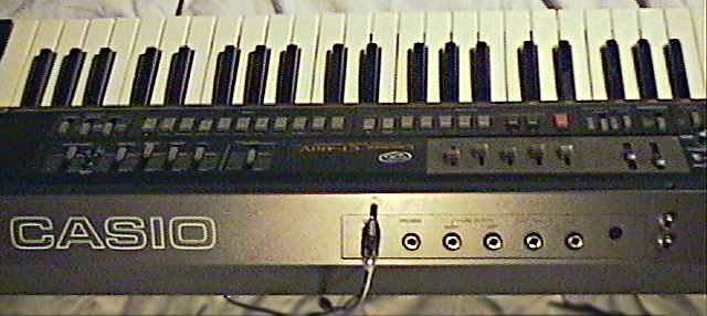
 Casio MT-400V (This is an eBay picture; I don't own one.)
The CT-410V/ MT-400V is by my knowledge the only Casio instrument with a genuine analogue VCF and analogue realtime sliders. Also the Casio HT series synthesizers HT-700, HT-3000, HT-6000, HZ-600 had analogue filters, but these are MIDI synths without realtime sliders. The HT-700 and HT-3000 had basically quite similar sound generation like the CT-410V, but with different and fully programmable accompaniment and PCM rhythm. The Casio HT-6000 was the flagship of these instruments and had for each polyphony channel even an own VCF and per channel 4 detuneable suboscillators those can be set to different velocity curves. I initially thought that the HT "analogue modelling" series would be virtual analogue and internally based on Casio's digital FM variant phase distortion (there were many such rumours), but the HT-series PCBs indeed contain analogue filter hardware with NJM2090 chips and many trimmers.
Because Casio MT-65/ MT-68 was the midsize instrument that uses most keyboard matrix functions of the "NEC D930G-011" CPU, I name this the MT-65 hardware class. There are plenty of other instruments with D930G/ D931C hardware those are usually cheap and easy to find at eBay, but they all lack the VCF and often many other features. Such instruments can be recognized by the rhythm and sound preset names (the sound names "funny" and "cosmic tone" are easy to remember) and also the count of 12 rhythms and 20 sounds and the possible presence of locking switches for multiple chord, bass and/ or arpeggio variants hint to it. Models with 49 midsize keys include the Casio CK-500 (MT-65 with 2 cassette decks, radio, only 12 preset sounds, stereo) the Casio MT-100 (aka Realistic Concertmate-600, with equalizer) and the Casio MT-45/ MT-46 (only same accompaniment, not main voice). Fullsize keyboards include the Casiotone 404/ 405 (complete MT-65 functionality, fake woodgrain case like Casiotone 401) and Casio CT-310 (49 keys, only 12 sounds but same accompaniment - all seen on eBay).
Also the Casiotone 7000 (silver metallic metal case with 61 fullsize keys, digitally programmable stereo chorus effects, sequencer with tape storage, LCD display, same 12 preset rhythms) is based on MT-65 hardware, although its 20 semi- OBS preset sounds have some changes because it is controlled by an additional CPU. I expected that also the 61 keys instruments Casiotone 610 (aka CT-610, similar with stereo chorus, woodgrain and silver version exists), CT-620 and Casio CT-605 (the latter mono with changed preset sounds) worked like this, but at least the CT-620 has a CPU with different software number to handle more than 49 keys ("NEC D930G-013" with changed keyboard matrix). Also the Casio MT-210 (49 midsize keys, stereo chorus, functions like CT-410V without VCF) and its fullsize version CT-430 have the typical controls, but some of the 20 preset sounds are changed because its accompaniment CPU has a different software number ("NEC D930G 019") and controls a PCM percussion IC. I first though that also Casio MT-800 and MT-85/ MT-86 (with ROM-Pack and key lighting) would be MT-65 hardware, but their accompaniment CPU has a different software number and thus are only the same family. The D931C sound chip was also used in the electronic guitars Casio DG-10 and DG-20 (seen in service manual).
A successor of CT-410V/ MT-400V was the Casio HT-700/
Hohner
KS 49 midi (has MIDI, but unfortunately sounds cold and lacks the
VCF realtime controls).
| removal of these screws voids warranty... | ||
 |
||
|
|