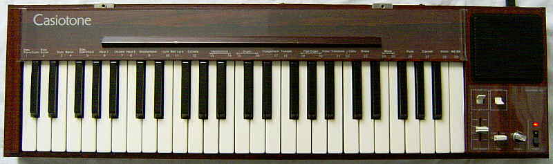
the world first Casio keyboard
(unusual semi-analogue sound)
|
the world first Casio keyboard (unusual semi-analogue sound) |
This quite heavy wooden thing from 1980 was the world first music keyboard ever created by Casio, and also constitutes basically the world first digital sound bank instrument because it had already 29 partly unusual preset sounds those are selected through the white keyboard keys. The "tone" switch offers 2 subtle timbre/ envelope variants for each sound and thus doubles the number of presets to 58 sound in total. (But this old instrument had no rhythm yet.)
 |
 |
Also a black version with grey control panel was made, and a fully black version (with reinforced metal corners and no rounded bottom rim, seen on eBay).
 |
 |
 |
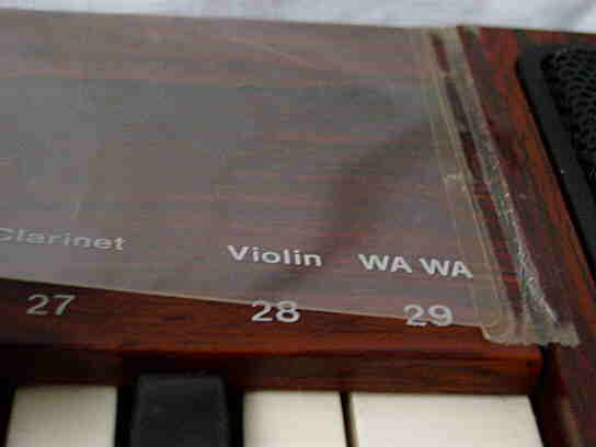 Sound names are only on the overlay; the numbers on the wood case.
 |
 |
Like with Casio MT-60 and CT-410V the sounds consist of mixed stair waveform suboscillators with different pulse patterns and different digital volume envelopes, those are (depending on the preset) muffled by different filter capacitors. But while the latter use sophisticated envelope controls, the Casiotone 201 and MT-30 use for its 2 suboscillators only very simple attack- decay envelopes. In the bass range many sounds turn into a more or less buzzy, sonorous purring drone, which is a characteristic style element of squarewave based instruments. These basses can resemble some of the famous POKEY sound effects on Atari XL homecomputers and are very different from the gradually duller and duller growing sine wave bass behaviour of average Yamaha FM keyboard sounds. (For further technical details about this hardware family also see here.)
Like the later MT-60, most sounds are rather bright and use apparently only a few different filter settings. But in comparison to the MT-60 most sound preset of the MT-30 are rather boring attempts of imitating acoustic instruments, those don't sound natural anyway (except with flute- like instruments), and by the lack of complex envelopes there are also no gimmicks like ringing mandolins. But due to the 2 suboscillators and filters they sound at least less plain than e.g. the timbres of a Letron MC-3. Due to the muffling filters, the bass range of various sound presets is too loud in comparison to simultaneous high notes.
The sounds are not bad, although most of them have rather little to do with their names. When not otherwise mention, I describe here the versions with "tone" switch set to 1. Interesting is that Casio named the only piano sound here "Elec. Piano" - likely because they knew that this hardware can not imitate a piano well - however it sounds more like a sonorous e-bass or tuba. The same sound is used as "cello" with a different envelope when the "tone" switch is on 2, despite there is a dedicated "cello" preset. The "Elec. Guitar" is a little brassy and also the "Koto" sounds similar. The "Banjo" sounds brassy too and has a long sustain phase that fades silent with rather low volume. The "Elec. Clavichord" is almost the same, only with a louder sustain phase. The "Harp 1" has a too long attack phase and thus doesn't sound percussive enough. The "Harp 2" resembles rather a dull reed organ that slowly fades silent. The "Ukulele" otherwise sounds like a harp. The "Glockenspiel" is not percussive enough and also rather a fading organ tone. The "Lyre" sounds ok (small harp) and also the "Bell Lyre" sounds harp- like. The "Celesta" is more a Rhodes piano and not very percussive. The "Harpsichord 1" and "2" sound quite ok and contain a metallic (aliasing?) overtone. "Organ 1" is a multipulse squarewave timbre and resembles a dull and bassy reed organ. "Organ 2" is a less dull variant of it. "Fluegelhorn" is a brass timbre (like intended) with a little buzzy bass range. The "trumpet" is rather dull and could be also a dull reed organ timbre. Both "Pipe Organ" timbres are quite bright, like metal organ pipes. The 2nd one is very bright and contains a chorus effect (tone=2 =>brighter without chorus). The "Viola" contains a chorus effect (which vibrato gets faster during higher notes) and with tone=2 it is duller and called "Thrombone". The "Cello" sounds static and could be also a brass timbre. The "Brass" is quite dull and resembles more a dull reed organ timbre. Both "Wood" timbres likely shall be wooden pipe organ timbres and sound quite ok. "Flute" and "Clarinet" sound quite realistic. The "Violin" has a rather slow attack phase is too dull and could be also some kind of flute although it fades silent after a while. The "WA WA" is a sweetish sort-of human voice made from 2 crossfading tones singing "wah" (and slowly fades silent); high notes rather resemble a flute. When not otherwise mentioned, the "tone" switch varies most sounds only gradually (e.g. duller or brighter or with/ without chorus).
Additional to the official preset sounds there are 9 electronic waveforms (some as tones, some with short decay envelope) on the black keys 11..19, including sine, trapeze and triangular wave. Unfortunately these sound very quiet because (when unmodified) the filters stay close.
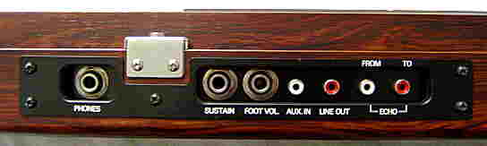
When sustain is off, all sounds stop almost immediately after releasing the key, which is particularly annoying since this instrument has no sustain switch and can activate sustain only by pedal. The sound presets itself also contain neither vibrato nor tremolo (but some a chorus, likely implemented by detuning on of both subvoices). Unfortunately even with sustain here a trilled note does not occupy new sound channels which on other ancient Casio keyboards (e.g. MT-30) produced a great phasing sound and volume increase effect.
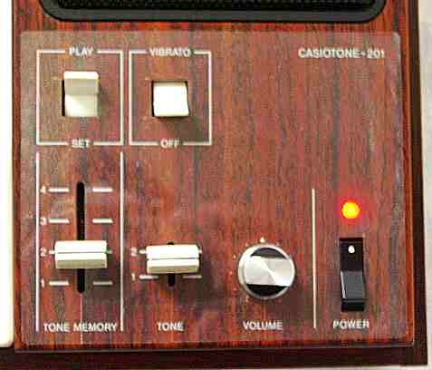
To select sound presets, the "mode" switch has to be moved from "play"
to "set", which will also assign the selected sound to the current position
of the "tone memory" switch. The sounds are then selected by white keyboard
keys. Very interesting is that the selected sound is played as a hint during
the selection key press, but only when the key is held down longer than
about 0.2s. (It's a pity that this trick is not used on average toy keyboards,
because the delay would make it possible to rapidly select OBS sounds during
live performance without hearing the selected sound, and despite easily
test the sounds by pressing the buttons slightly longer.) When the "mode"
switch is set back to "play", the keyboard behaves normal again (and the
"tone memory" switch can select between 4 of these sound presets during
play). After power on, the 4 "tone memories" contain the sound presets
{Elec. Piano/ Cello, Harp 2, Organ 1, WA WA}. Only the white keys are used
to select sounds; possibly an external ROM chip with additional sounds
for the black keys was planned, because pressing most black keys apparently
selects here an empty sound because it mutes the keyboard. Otherwise on
the leftmost 3 black keys are the preset timbres "Harp 2", "Organ 1", "WA
WA", those correspond to 3 of the default sounds. Strange is that this
"Harp 2" is a little quieter than the normal "Harp 2" sound from the white
key number 8. In practise the "tone memory" switch is rather useless, and
it also makes no good realtime sound effect since it responds with a delay
of about 0.25s.
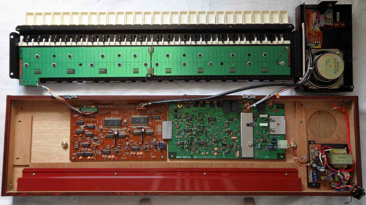
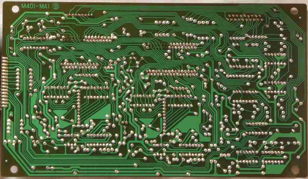
circuit bending detailsThe Casiotone 201 is based on 2 almost identical CPUs D771G and D772G, those are likely LSI made from gate logic and not actual microcontrollers.
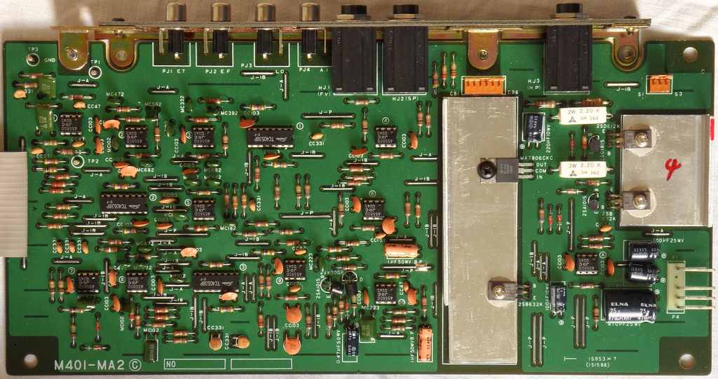
Unusual is that the keyboard matrix is polled by both CPUs those are mostly wired parallel. Both CPUs do exactly the same but have (in the manner of SIMD vector computing) different sound rom data. So each CPU outputs its polyphonic digital audio (that per channel is already made from 2 subvoices with each a digital volume envelope) through its own 14 bit DAC and a switchable fixed analogue filter to modify the timbre. Finally the analogue output of both filters is mixed together to form the sound signal. The filter settings are static and do not change during envelopes (likely to avoid dependencies between polyphony channels). Apparently one CPU can use the normal and the other a spread chromatic tone scale to produce a chorus effect (phasing) when layered. Casio named this system Consonant-Vowel synthesis (abbreviated "CV" - possibly to puzzle the analogue synth community, where CV is normally "control voltage"), naming the subvoice of one CPU "consonant" and of the other "vowel". Most waveforms are composed of symmetrical straight and ramp sections and look quite geometric. Only the sine wave looks as round as the coarse step resolution permits. Like with the later D931C, (which was detailedly researched by Robin Whittle) the sound generator apparently can not only mirror the waveform in hardware, but also skip either the positive or negative halves or even pass only every n-th wave cycle (i.e. a wave is followed by multiple wave lengths of silence) which creates the typical buzzy bass range known from squarewave based instruments. Unfortunately the employed waveforms in this mother of all Casiotones use mainly simple symmetric ramp patterns those don't sound too great. (Successors sound better.) I don't understand why Casio didn't use more asymmetric waveforms like a real sawtooth to imitate a trumpet. The "Tone" switch seems to be no digital control at all, but simply switches through some gates the fixed filters (making e.g. one suboscillator duller and louder). Although these filters use lots of components and 13 CPU control pins (D771G uses pin 40..42 & 44..47, D772G uses pins 42..47), they sound neither spectacular nor make timbres particularly natural, so their complex design is quite a waste. I think it doesn't sound by magnitudes better than an MT-30 (which filter is controlled through only one pin), but who knows - perhaps some electrolytic capacitors have gone bad. The unfiltered audio from both CPUs can be tapped individually at the test pins TP1 and TP2 on the analogue (green) PCB. The hardware is crystal clocked (4.536688 MHz). Caution: This instrument has an ungrounded power supply. These tend to charge itself with static electricity at half mains voltage; although harmless for humans, it may be sufficient to destroy irreplaceable ICs by ESD. Thus if you connect any grounded devices (like amplifier, oscilloscope, PC) to the PCB during operation, always wire GND first to prevent discharge across IC pins. The sound generation for the 8 polyphony channels is time multiplexed, thus like in most later 1980th Casio keyboards, all register contents of sound and envelope hardware is genuinely stored in 8 stage circular multi-bit shift registers. As a form of lightning fast hardware multitasking, after processing each channel they cycle to the next entry every clock step, so a task runs every 8th step and outputs its audio increment to an accumulator that finally sums them as a 14 bit DAC output value. Also this is a Casio speciality - who knows if a foreign patent prevented them from using address counters for cycling through sound channels, but shift registers may be also just a proven concept from calculator design they were most familiar with. The concept of this instrument is described in the US patent 4283983 (particularly focussing on the user interface with tone memory). It is based on logic gates and not software controlled. The circuit for sound selection through keyboard keys (with waveforms and envelope hardware) is detailedly explained in US patent 4348932, and the part for sounding a demo note (and improvements like layered sounds) in 4387619. In the nicely detailed reference implementation of patent 4348932 the keyboard input from the key matrix decoder is demultiplexed and then one line per key is running into a code converter (simple sort of ROM without address decoder) which outputs for each key number a 6 bit note frequency and 12 bit sound definition data for the preset sound selectable through that key. During sound selection the sound definition data is written into a register that controls waveform and envelope generator. And the described envelope generator is truly bizarre, because by the lack of multipliers it can not(!) change volume and waveform independently. Each waveform consists of straight and ramp sections (like sawtooth) of fixed steepness, so the amplitude can increase only by making that ramp either grow row by row ("fixed mode", like building a brick pyramid bottom-up) or dive up peak-first vertically out of the zero line ("floating mode"). A waveform is always 32 steps long and up to 15 steps high. Said 4 bit volume envelope consists of 5 linear sections {increase, transform, decrease 1..3} with different clock rates to roughly approximate logarithmic shape. All envelope clocks are derived from the pitch clock. During "increase" (attack) the waveform always grows in fixed mode (like opening a voltage limiter), during "transform" at full height it morphs into another waveform (square, ramp) with intermediate shapes looking like one waveform cut out of the other (like y=min(wave1(t), wave2(t)) ). The "decrease" steps can either make the waveform shrink vertically like closing a voltage limiter (fixed mode), or make it sink into the zero line (floating mode, peaks stick out last); a square wave pulse can even shrink also horizontally (floating mode, of course making the blank section longer to keep the same frequency). The whole morphing waveform generator works by adding/ subtracting steps at a certain clock rate to the amplitude; what is done in which section is switched by gates at certain waveform step numbers (of 0..31) and a comparator that compares the actual amplitude with the waveform step number and so switches addition or subtraction of clock pulses to the amplitude counter. Both halves (the part before and after step 16) of a waveform can morph independently, but a ramp in the first half is always ascending, in the 2nd half descending, so they can form a triangular wave. A square in the 1st half stays zero and has the pulse at the start of the 2nd. The described preset sound definition uses 2 bits for 4 settings of the fixed analogue filter, 3 bits to select 5 different envelopes, 5 bits to select 18 different waveforms and 2 bits to select 3 octave shifter settings. The output DAC has only 7 bit. But this reference implementation substantially differs from the finished instrument. E.g. it lacks vibrato, sustain pedal and tone memory, and supports only 48 keys. The "Tone" switch is digital (i.e. 2 preset sounds for each key stored in the code converter for up to 96 sounds in total). "Tone" and sound select switch are outside the keyboard matrix. And instead of one demo note it even sounds a sequence of 3 (C4, C4#, D4) - a gimmick that was not implemented until the (technically very different) CT-8000 of the Symphonytron stage organ. The reference implementation even seems to use only positive half waves and may lack the mirroring mode for symmetric waveforms. The actual Casiotone 201 IC supports 8 instead of only 2 filter control outputs and its envelope generator definitely can change amplitude (likely logarithmic using a ROM lookup table) without morphing the waveform. It doesn't seem to distort all attacks by simulated voltage limiter envelope, but rather add a 2nd waveform (symmetric, i.e. quaterwave definition read out of ROM?) with short decay envelope to imitate things like string pluck noise of acoustic instruments. Several of these short waveform blips are eastereggs on the black keys, as well as even an unused sine wave, which may be even there for internal computation, because US patent 4453440 mentions a fast multiplication method based on subtracting 2 phase shifted versions of the same sine wave read from a ROM lookup table. Possibly also the bit shift multiplication network from US patent 4590838 (D931C predecessor) is used. While I don't see the pure morphing envelopes from patent 4348932, various preset sounds employ trapeze waveforms those may be indeed based on a triangular wave truncated by a vertically mirrored static version of said "fixed mode". In other sounds it even morphs a triangular wave by the "floating mode" sinking motion. So it may be that Casio indeed layered a modified version of their morphing waveform generator as the "vowel" with a technically different, ROM based attack waveform as the "consonant", hence the name "Consonant Vowel Synthesis". The concept of geometric waveforms those gradually change shape by growing out of the floor or being truncated from one side to modify timbre has very strong similarities with the "paper sound" technique that exposed paper cut shapes as waveforms on film to be played as the sound track in a film projector. Also here timbres were modified by gradually cutting shapes by means of stopmotion cartoon animation (e.g. by moving a black shade over parts of the bright waveform). On the same idea the Russian Evgeny Sholpo created in 1930 the optical synthesizer Variophone - a mechanical contraption with waveforms on exchangeable spinning cardboard tonewheels that was used to compose polyphonic music for cartoon movies that sounded surprisingly similar like chiptunes. Nevertheless that a Casiotone 201 doesn't sound overly great, it would be fascinating to simulate the original morphing waveform envelope generator of the patent 4348932 prototype in software (or perhaps even FPGA) to explore what it sounded like. This was the mother of all Casio keyboards, and this bizarre piece of minimalistic gate logics design without multiplication is so Pong-age - a weird chip invention like Atari Video Music that deserves to be preserved. US patent 4387619 poorly describes a later variant of said reference implementation; the sound and envelope generator here supports 84 keys, an 8 bit DAC, vibrato and sustain. Its implementation is much more complicated (twice schematics size) with plenty of multiplexing, involving e.g. instead of the code converter a ROM followed by a bunch of gate logics to translate its 8 bit output into 13 control bits. Main reason for this was likely to implement a so-called "staggered multi-performance mode", i.e. a preset sound can consist of multiple layered subvoices occupying 2 or 4 polyphony channels ("duet", "quartet" - a feature that was not released until the much later "unison" modes in the CPU controlled Casio CT-6000), which needs independent management of key presses and polyphony channels. In an LSI chip without software control the routing is quite a mess - involving plenty of additional shift registers to memorize which key press belongs to which sounding note and such stuff. The master clock is stepping the shift registers with 1MHz, which permits rapid 8µs polyphony multitasking. The preset sound definition in ROM here uses 2 bit attack, 2 bit release, 2 bit period ( = pitch?), 1 bit delay, 3 bit waveshape designation (1 bit = fixed/floating, 2 bits select sawtooth, rectangle, triangle), 1 bit vibrato, 1 bit octave. But this system looks even more restricted than the first implementation - allowing only linear attack-decay envelopes without held notes (this resembles MT-30), and apparently the "floating" triangular wave is gone. Worst is it lacks the transform effect. At least waveforms have here 64 steps (center at 30) with 30 step height, and the delay bit can make the triangular wave asymmetric by slowing down attack. Unfortunately this patent text doesn't explain much, but rather describes wiring in lengthy sentences and omits details (like ROM data format), which makes it hard to understand. The key feature of this circuit is apparently the "staggered multi performance" mode, which loads 1 or 3 additional preset sound definitions from ROM as subvoices; 2 bits "minute difference" (+1/64, -1/64) apparently allow to detune these for chorus effect, 2 other bits set their octave range. This sound generator supports 7 octaves, but the highest one cheats by only repeating the 6th octave (foldback) with waveform changed to "floating sawtooth". The delay bit here apparently can delay a subvoice, and when with "quartet" multiple subvoices set this bit, the delays accumulate to make them sound one after another. According to the text, apparently the circuit is multi-timbrale enough that selecting a new preset sound would not affect held notes (201 can't do this), and other parts (mentioning "12 scales", perhaps poor translation) sound like that it can even transpose. The demo note (named "sample tone") here is indeed a single note. The digital vibrato is implemented by making a frequency derived from the clock add and subtract 1/64 (i.e. 1 waveform step?) to the waveform. But also this implementation does not describe a finished instrument. E.g. it supports 84 keys, does not have preset sound selection through note keys (only mentioned as optional variant), no filters and has switches for vibrato, sustain (aka hold pedal?) and demo note on/off placed outside the keyboard matrix. Interesting is that the "minute difference" effect in layered preset sounds uses for chorus the same addition of +/-1/64 like the vibrato circuit. In the actual 201 the phasing disappears (at least on one channel on my scope) when vibrato or spread scale is on, so they obviously share the same internal resources. However the 201 does not reduce polyphony in any preset sounds, which proves that it is not based on the "staggered multi performance mode". Interesting is also that Casio refers internal polyphony channels as "lines" - a term that was later used for PD synthesis. At this time Casio patented a lot of things those didn't make it into the final instrument. E.g. US patent 4476766 (priority date 1980) describes a key split mode with simple "any key play" sequencer to manually step with 2 key groups through each a previously recorded main and "accompaniment" (rather obligato) voice. The note data is stored here as key matrix signals (12 keys in each of 4 octave groups) in 2 RAMs. Although with timers it could recognize simultaneous notes (e.g. chords) to be stored as one step, it did not store note or pause duration and thus could not do autoplay, nor there was edit. The illustration drawings blatantly resemble 201. US patents 4522100 and 4594931 were a simpler variant without 2 simultaneous timbres; US patent 4361067 even describes a variant with playback volume change using different keys (instead of velocity) during "any key play". These 3 could also set the keysplit point through a simultaneous switch + key press (not bad for simple gate logics). Although these patents already mention loading note data from external means like barcode or RAM-packs, the first remotely similar feature in a finished product was the "one key play" in the monophonic Casio VL-1 (which had edit and autoplay), and even the barcode sequencer of VL-5 was still monophonic. keyboard matrixI haven't analyzed the Casiotone 201 fully by myself, but Robin Whittle wrote in 1980th a great technical bulletin "Modifying the Casiotone Instruments" with many technical details including keyboard matrix. The matrix is from D773G but seems to be identical in all D77xG based polyphonic Casio keyboards (only preset sounds differ). In the 201 the matrix is polled by both CPUs (one writes, both read) those are mostly wired parallel; I verified that its matrix places for function switches behave like Whittle's description, although he made some errors (the C4 key doublets don't seem to be strange behaving and the 'tone memory' numbering either was wrong or differs among keyboard models). A little illogical is that the C5 key is placed in the matrix where you would expect the C1 (later Casio keyboard generations fixed this).Various keyboard matrix signals are amplified by logic ICs (perhaps to avoid polyphony flaws by too weak CPU output lines, timing glitches or as overzealous ESD protection). Likely it is the principle like in Casiotone 202, which buffers the inputs in a bank of flipflops to ensure that both CPUs see always the same key presses. The "Tone" switch is not part of the matrix, because it only controls
the analogue filters.
The keyboard matrix input lines are active-low, i.e. react on GND, thus
any functions are triggered by a switch in series to a diode from one "in"
to one "out" pin.
Robin Whittle writes about D773G that the doublet keys at CPU pin 18 behave strange; they use a different sound channel than their normal versions, and combined with 'octave down' some of them (here marked "o´") change pitch during play, which is affected by vibrato and tone memory settings. In my Casiotone 201 and 202 I verified the behaviour only with "strange" C1 but no C4 keys. I suspect that these matrix places may have been designed for a kind of binary input method to be controlled by e.g. an unknown (never released?) accompaniment IC (using pin 34 and 39?). But it also may be that by a lookup table bug they fetch their note pitch from internal RAM instead of ROM and so produces semi- random nonsense when the RAM cell is used for something else.
CPU pin 17->30
Robin Whittle wrongly claimed this feature would only exists in the D773G CPU, but I found it also in Casiotone 201 and 202.
CPU pin 17->27
CPU pin 16->26
CPU pin 17->26
CPU pin 17->25
CPU pin 16->25
CPU pin 16->31
CPU pin 18->29, 18->30
pinout D77xG familyThe "NEC D77xG" (64 pin zigzag DIL) was Casio's first polyphonic keyboard CPU that was used until 1981(?). It contains a keyboard matrix decoder with 4 quick access memory settings for favourite preset sounds, those are normally selected through keyboard keys + select button, but this selection method can be also simulated by preset sound buttons connected through logic ICs (like in Casiotone 401; pulling pin 34 hi seems to mute the demo note). The sound generator is 8 note polyphonic with digital envelope and stair shaped waveforms those sound much like multipulse squarewave. The 14bit digital audio output is fed into an external resistor ladder DAC. Each sound is made from 2 layered subvoices with independent envelope, what Casio called "Consonant-Vowel-Synthesis". It can additionally select timbres through an external analogue filter circuit controlled through 8 digital switch outputs. 2 of these CPUs with different software number can be wired parallel (one polls the keyboard matrix while both read it) to produce more complex layered preset sounds (4 subvoices using 2 filters). The tone scale can be switched from normal chromatic to a slightly spread variant which produces a chorus effect when 2 layered ICs set it differently. Clock can be input at pin 37 and output from pin 35 (half speed) daisychained to another CPU, or pin 35 is used as input. Bizarre is that this special CPU contains an LCD display port that is not used in any Casio keyboard (nor would it make sense in LCD pocket calculators due to size and power consumption). The CPUs in my 201 run a little hot - possibly because the digital supply voltage has 5.2V instead of the expected 5V and the analogue supply voltage is even 6V. In Casiotone 202 both have only 5V.The naming convention of this earliest Casio keyboard CPU family is
horrible; instead of software numbers the main number increases without
any logical structure. It may be that advancing the 2nd or 1st digit reflects
envelope algorithm changes or size of internal memory, but it also may
be simply derived from the release date. According to Robin
Whittle, all these ICs seem to differ only in their preset sound set
and subtle changes like whether they can do sound selection without playing
a demo note. He later called the hardware family 'Series I', but I prefer
'D77xG' despite it contradicts the naming in later keyboards.
Like with most special Casio ICs there are no datasheets online, but with modern NEC ICs the prefix D77 is used e.g. for 16 bit fixed point DSPs, D78 for generic microcontrollers (like D7811G) and D990 can be digital codecs, so it even may be that these CPUs are (e.g. by Allen's patent lawsuit) internally completely different and only share their pinout. But the very similar sound and behaviour of affected keyboards make this unlikely. Modern NEC IC types have a huge variety of variants and their numbers are longer, so it may be that in 1980 the naming convention did not exist yet and diversified during the following few years which resulted in changing prefix numbers within one family. It is interesting that all other NEC D77x ICs are single-chip videogames containing a CPU with internal ROM and RAM. So D770C was a Pong clone (tennis, soccer, table tennis, solo + 2x shooting). D774C (42 pin DIL), D777C ### and D778C were cartridges for Epoch - Cassette Vision; despite very limited rom space, this busless microcontroller supports 48-bit instructions, which made it faster than 8-bit CPUs with external rom. D779 was the graphics+audio chip of Hanimex HMG7900 (which cartridges contain another microcontroller). It is unknown if there are any technical similarities to Casiotone, or if NEC IC numbers were simply given by date of development. Strange is that while on internet photos I saw a Casiotone 403 with CPU D990G, its service manual refers to D776G and shows a somewhat complicated flipflop and gate logic network named "set control circuit" (involving ICs TC4013, TC4049, TC4073, TC4081, 74LS123 and 2 transistors), that during active "set" switch enables the keyboard matrix place "memory set" (SI2->KC3), and once a key is held, after a 2..10ms delay it plays the "A2" demo note (connecting KI4->KC4) and then disconnects SI2->KC3 (return to play mode) to prevent data mess when more than one key is depressed during memory set. In that circuit the "set" switch output is additionally connected through an inverter to CPU pin 34 I-2. The page comes with the note "This circuit prevents to preset another tone when hitting more than two keys while the MODE switch is at "SET"... This circuit is employed only in the initial lot of Casioton 403. Later produced 403 enclose the circuit within the LSI." So apparently early D77xG versions need external bugfix circuitry to function properly, which explains the lots of logic ICs inside Casiotone 201 despite the CPU concept is quite self-contained. I had no schematics, so this D773G pinout was based on Robin Whittle's
great bulletin "Modifying the Casiotone Instruments" which is not
very detailed and lacks most pin names, so some pin order within equal
named blocks are a guess and (particularly 40..43) may be wrong. Despite
I later got service manual photocopys of MT-40/ MT-31, Casiotone 403/ 101,
401 and 202. Even in their schematics unused pins are omitted, so some
pin names were chosen by me. Apparently all "O-#" pins are outputs, "I-#"
are inputs and "IO-#" can be both.
Robin Whittle describes pin 40..47 very ambiguously as "O-29 to O-31 and IO-4 to IO-8, used for filter, volume and LED control in different ways. Pin 46 controls filter cutoff frequency in the M-10". I measured that these pins output an individual static combinations of hi and lo (like a binary number) to identify each preset sound so long it stays selected. Pins 39..47 generally seem to need a pullup resistor to be useable. The Casiotone 202 PCB uses all these pins to control its filters; its D771G uses all but pin 43 and the D772G pin 42..47; the CPUs themselves output to all of them. Pin 39 goes low during any preset sound select ('memory set' or 'tone memory'), which is used to mute the main voice as a pop noise blocker; however the edges of the pulse have a strange jitter that may be serial data encoding the preset sound number. Pin 34 is (according to Whittle) only used in Casiotone 301 (also my similar 401; Casiotone 403 service manual says "Input from SET switch"); it may be a serial input to select preset sounds from its OBS buttons. I don't know if it can even receive synthesis data like the later D931C; particularly the fact that in US patent 4348932 the preset sound definition itself (and not only a pointer to a ROM address) is held in a register during execution suggests that there may be hidden functions for this. The mysterious LCD port seems to output the selected preset sound numbers. There are plenty of 3V squarewaves on these pins, of those some (the active segments?) halve their frequency. With set 'memory set' switch some segments seem to blink. Pin 13 and 14 have a stepped waveform from 0V to 1.5V to 3V vice versa, that apparently is the return pole for an LC display. If you want to install a homemade LED display here, I strongly recommend to use driver ICs, because these irreplaceable CPUs run already a little hot and may get damaged by additional current. (I haven't tried to connect a display.) I found no official specification of the D77xG. The only text that comes close to it is (here slightly edited) what Robin Whittle wrote in that bulletin about the inner working: "The LSI has four input/output sections:
Voices such as organ and flute have a fixed waveform that increases linearly in volume, stays at the maximum volume while the key is held, and decays at half the initial rate when the key is released. The attack and decay rates are doubled for a note an octave lower - indicating that the volume register is clocked by the waveform. If the sustain switch is closed, the decay is much slower and unrelated to pitch. Other voices exhibit more complex behavior - they may start at maximum volume, or increase volume with one waveform and then abruptly change to another, as in the MT-30 'Funny Fuzz'. The voices which change timbre seemingly do so by varying the volume of two different waveforms which are summed to form the total. There seem to be 32 time divisions per wave and at least 32 linear volume steps. Most of the waves are quite geometric, suggesting that they are defined by gates rather than ROM. Vibrato is applied to all notes simultaneously by lengthening and shortening some of these sample times and then further shortening the shortened ones to cause the vibrato. It seems to me that each waveform is the sum of two processes, in each of which a 32 sample 5 bit waveform data stream is multiplied with a 5 bit volume register to form 10 bits. These two are added to produce the 11 bit waveform for that sound channel. The outputs of the eight sound channels are added together to form the 14 bit total output. An interesting way to observe these processes is to turn on the MT-30, turn the volume up full and without playing a note put the speaker to the ear. [...] What I hear in mine seems to be all 8 sound channels playing the current voice at one pitch; if I play a few notes the sound no longer has such a distinct pitch. All these waveforms are going on all the time but the volume registers are zero. The stunning fact is that the output is accurate in the time domain to one clock cycle - 1.763 µsec which represents a data rate of about a megabyte per second [...] I have now concluded that the uPD77x LSI's are most likely composed of hardwired logic and memories and probably do not contain a computer, which casts a shadow of doubt over the title of this paper [which ended on "...the smallest computer instruments"]." The text then mentions a patent lawsuit by the Allen Organ Company of Pennsylvania against Casio, complaining that Casio's polyphonic instrument chips were "partly photographic copies" of a chip developed by Rockwell in 1971 for the Allen 'Musically Dedicated Digital Computer' (a digital church organ). If you want to modify an instrument of the D77xG hardware family, it is very recommended to read the full bulletin, which contains much additional info about DAC improvement, noise reduction, clock speed hacks and building an asynchronous keyboard matrix interface to layer multiple Casio keyboards or control them by homemade (non-midi) digital hardware. Whittle seems overly cautionous with suggesting to install additional driver ICs to protect the CPU from static electricity (soldering the usual diodes from GND to each affected CPU pin and from there to +Vs should be enough). Otherwise I can only warn against his recommendation of using epoxy resin glue since it is severely poisonous.Successor of the D77xG family was the famous D931C sound IC, which very similar waveforms are software definable through a host CPU. |
The direct successor of this instrument was the Casiotone
202 from 1981, which sound bank had even 49 sounds at a time where
other preset keyboards still had maximum about 12 or 20 preset sounds.
But this one had no selectable envelopes anymore (which basically doubled
the number of sounds), a great feature that was re- introduced only later
with the Casio MT-65 hardware class (see CT-410V).
A technically much simplified single chip variant of the Casiotone 201
hardware was the Casio MT-30. The
first Casio keyboard with accompaniment was the Casiotone
401.
| removal of these screws voids warranty... | ||
 |
||
|
|