|
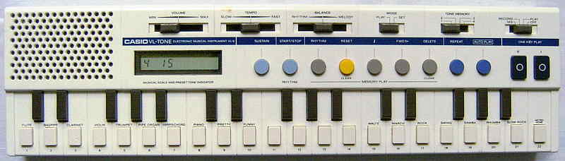
This quite rare keyboard of 1982 (concluded by advert and barcode songbook dates) was the polyphonic successor of the famous Casio VL-Tone 1. Unfortunately it is missing the great built-in synthesizer, the octave switch and even the natural violin sound of the VL-1. Instead it has only 10 simple preset sounds. The rhythms are more complex but awkward to select. By an optical barcode reader pen (Casio MS-1) songs can be scanned from special barcode song books into the internal sequencer memory. The sequencer is only monophonic, but at least you can manually play to it.
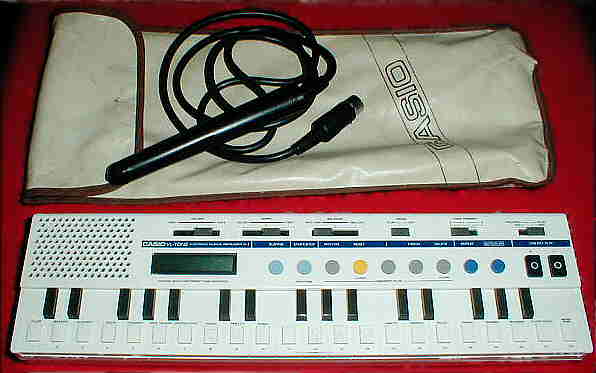 This is an eBay photo; mine lacked bag and barcode pen.
 |
 |
 |
 |
Unlike my expectation, the sound generator is not exactly like Casio VL-1 (see there), but has stair waveforms instead of only multipulse squarewaves. Unfortunately uses far simpler preset sounds and has no synthesizer. Some timbres are muffled through capacitors. The sounds contain neither vibrato nor tremolo and seem to employ only a simple sustain/ decay envelope. The "violin" has here no similarities with the astonishingly realistic VL-1 one, but is just a slightly harsher version of "flute". The "pretty" sound is a sort of simple xylophone with short decay envelope and pulse ratio 1:1. The "funny" sound is a harsher version of this and resembles the "guitar" on VL-1. With sustain off, all sounds stop almost immediately after key release. With sustain enabled, as well the release phase as the decay of decaying sounds are lengthened to about 3s. The sustain button also affects held and currently decaying notes, which can be used for live play tricks.
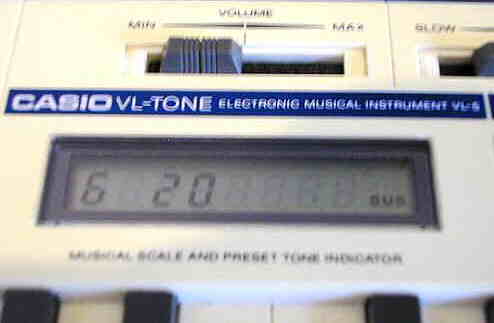
The LCD displays the current preset sound and rhythm number so long the sequencer is not in use. Like with the ancient Casiotone 201, to select sound presets the "mode" switch has to be moved from "play" to "set", which will also assign the selected sound to the current position of the "tone memory" switch. The sounds are then selected by white keyboard keys. Unlike other such instruments (e.g. Casio MT-60), here selected sounds always play immediately, and not only when their key is held down longer than about 0.2s.
Also rhythms are selected by keyboard keys, but unfortunately (unlike
the VL-1) the rhythms here can be only selected in the "set" position of
that switch, which always starts that rhythm, but stops it again by pushing
the switch back to "play", thus to select a rhythm you have to move the
switch, press its key, move it back and press "rhythm start/ stop", which
is really awkward. At least there is a great analogue tempo slider with
that the rhythm speed can be adjusted from very low to partly extremely
high. The rhythm tempo of the individual rhythms varies a lot (likely depending
on the internal rhythm pattern resolution), thus while some rhythms (e.g.
waltz) can be set only fairly fast, others (slow rock...) turn into a furious
jungle drumroll pattern. The percussion is only made from simple squarewave
blips and shift register noise, but unlike the only 3 sounds on the VL-1,
here a great variety of different blips is used. It is especially astonishing
how many different "drum kits" Casio used among the only 8 rhythms;
while some are made from only long sounds, others consist of only very
short percussion blips. Like the great Hing
Hon EK-001, these rhythms sound very impulsive and are great for
tekkno. It's really a pity that Casio gave this thing only 8 rhythms
with such an awkward selection method - a programmable custom drummer (like
e.g. on Letron MC-3) would have been nice.
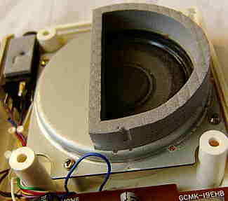 Like
the VL-Tone 1, also the VL-5 features that strange built-in speaker
that permits to bend the sound in strange ways by simply moving the left
hand over the speaker grill during play (similarly like jazz trombone players
do with their instrument's funnel). In the VL-5 the speaker resonance pot
is a unique construction formed by a moulded case cavity in combination
with a very odd sheet metal can that covers the lower half of the speaker
diaphragm behind the piano keys. The wahwah trick works especially well
with the VL-5's harsh "bagpipe" sound, but by the missing octave switch
it can be unfortunately not transposed as low like on the latter although
with polyphonic sounds it gives the whole thing a quite different exciting
quality. Like
the VL-Tone 1, also the VL-5 features that strange built-in speaker
that permits to bend the sound in strange ways by simply moving the left
hand over the speaker grill during play (similarly like jazz trombone players
do with their instrument's funnel). In the VL-5 the speaker resonance pot
is a unique construction formed by a moulded case cavity in combination
with a very odd sheet metal can that covers the lower half of the speaker
diaphragm behind the piano keys. The wahwah trick works especially well
with the VL-5's harsh "bagpipe" sound, but by the missing octave switch
it can be unfortunately not transposed as low like on the latter although
with polyphonic sounds it gives the whole thing a quite different exciting
quality. |
In the ancient home computer magazine "Your Spectrum" (Issue 4, June 1984) was an article about connecting a Sinclair ZX Spectrum home computer with the barcode reader input of a Casio VL-5. This article contains a BASIC program and many technical details about the data format of the Casio barcode song books, and it says that the same program works also with the Casio MT-70. The article can be found here.
The simple sequencer is only monophonic. To program it, set the power switch to 'record'. The LCD displays now in the middle the current step number of the editor. To the left you see the current preset sound number and to the right the current note or sequencer event. Press 'reset' together with 'delete' to clear the memory contents. Now play notes with the keyboard. Enter pauses with '}' and the rhythm start point with 'rhythm' button (those enter a special character instead of the note number). Wrongly entered notes can be removed with 'delete'. At the end you can press 'reset' and step through the song with the 'one key play' buttons to enter the correct note lengths. You can also insert new notes here or delete unwanted ones. To step forward through the song without changing note lengths press 'fwd >'; unfortunately this doesn't play the notes, which makes its use confusing. (With power switch in 'play' mode you can safely step through the song with the 'one key play' buttons without changing it.) Press 'autoplay' to play the entered song. Press 'repeat' and then 'autoplay' to repeat it in a loop. You can also manually play 2 note polyphonic to the sequencer contents. As well sequencer as the manual play both use the currently selected main voice sound and rhythm; you can not set independent preset sounds them. According to the manual there is a bizarre bug that can alter the last entered note in the sequencer memory so far certain conditions are not fulfilled (see eastereggs). Possibly notes were stored in groups of 4 in a temporary buffer and only moved into (non-volatile) SRAM when the 4th note was entered; so with less entered notes the remaining buffer content is eaten by auto power-off.
My first VL-5 was missing its barcode pen and song book, thus I have
tried out those from my Casio MT-70;
the VL-5 only reads the monophonic main voice part but refuses the chord
barcode lines (playing the error sound), thus I could only scan the monophonic
melody track into the sequencer. Later I bought a complete VL-5 specimen
(with box, pen and manual) which came with its original "Bar Code Score
Book" (see here
for song list); like expected, its songs are only monophonic and have no
chord section.
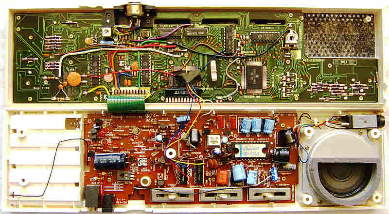
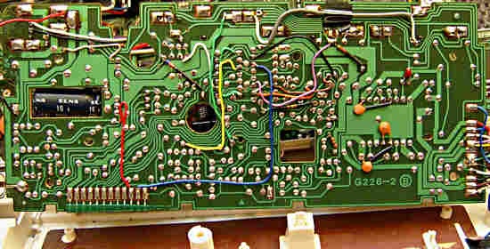
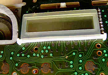
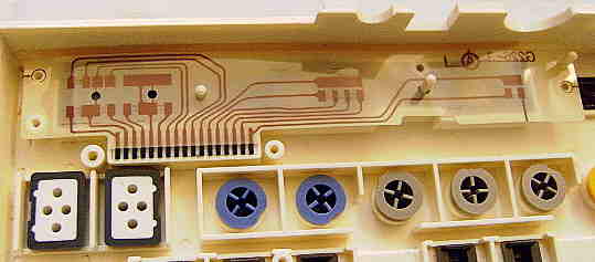
circuit bending detailsThe Casio VL-5 has astonishingly complex hardware, built around the ICs "NEC D910G 011" and "Hitachi HD43191A07". At least in my specimen it looks rather like a handmade prototype than a finished serial product, since it contains a lot of cut PCB traces those were manually re-wired with coloured cables and partly soldered directly to IC pins. Some of these loose wires affect the barcode reader hardware, but also the back of the analogue PCB is full of them. (The only other keyboard where I found such a lot of hand wired PCB fixes is the cheap Chinese Angeltone DM-200 toy keyboard.) But in opposite to the Casio VL-1, here the panel PCB already has carbon contacts under the buttons, and the LCD seems to employ an odd shaped silicone contact strip instead of the flimsy foil cable (despite this cable was still used in Casio PT-30 and many later models).
If a VL-5 randomly refuses to power on or doesn't turn the amp off, check the green ribbon cable; if pin 11 came loose, everything will work ok except that power-on reset will not wake the CPU after a crash. (Uncrashed it behaves normal.) Also my power transistor D439 was faulty (20 Ohm resistance between pin B and C) which distorted audio. (I replaced it with an old BD137?) Regard that the "P-" button at the case bottom is not a hard reset; although it clears memory, it will fail when the CPU has crashed too deeply, so you have to remove batteries to recover. I read in a forum that the SRAM "NEC D444C" (4bit*1K) is compatible with the modern counterpart "NTE 2114". keyboard matrixAnalyzing this keyboard matrix was really a hell job! Not only the traces on the double sided PCB change sides as if it was a sport (no chance without staring on backside photos), diodes are cluttered everywhere - some in input lines, some in outputs, many combined into 3 ICs LB1100 - and not least all outputs beside one are routed through 2 inverting driver ICs TC4049BP, which prevents measuring them directly at the CPU pins. Additionally the outputs are multiplexed with address bus, which makes crashes when shorted. The complicated diode chaos makes no sense; a row of upright 1N48 diodes near each button would not take more space and I never saw LB1100 in Casios again.Fortunately the TC4049BP and LB1100 at least have an individual numbered
label printed white on the PCB for identification. These are their pins
to access the keyboard matrix.
Regard that I don't have a service manual, so there may be still some
bugs.
The input lines are active-lo, i.e. react on GND. Any functions can
be triggered by a non- locking switch in series to a diode from one "in"
to one "out" pin.
Unfortunately I found no obvious ADSR synthesizer mode (like with VL-1),
despite the synthesis engine is RAM based and so can wake up with changed
sounds in tone memory after a crash. I expect that wiring an external microcontroller
to the bus may permit to edit sound data.
pinout D910GThe "NEC D910G xxx" (80 pin SMD, xxx = software number of internal ROM) is a 4 note polyphonic sound CPU with percussion outputs that was used as the main CPU of Casio VL-5 and accompaniment CPU of Casio MT-60. Apparently it was designed as a battery compatible replacement for the awkward combination of D8049C-084, D8243C and TMS3615 that in Casiotone 403 did accompaniment for the D990G. The D910G version "011" in can produce blip percussion, while "012" in MT-60 seems to output trigger pulses for analogue percussion and 4 note polyphonic accompaniment patterns. Bizarre is that on my VL-5 mainboard it even has the label "µPD910G12"; if this was no typo, it suggests that both versions may be identical and receive sound data from their companion IC. The main voice sound is output through an external 10 bit resistor ladder DAC, while blip percussion has an analogue output pin. The main voice is made from stair waveforms (ramp and rectangular sections) those here neither morph during decay nor are particularly symmetric, which unlike consonant-vowel synthesis hints to a simpler tone generator without flip and mirror functions and no subvoice. The waveforms can be 8 or 16 steps long and 5 or 9 steps high, and externally muffled through a lowpass filter (on or off). The synthesis parameters seem to be not entirely in ROM but programmable; after crash, the VL-5 often made different envelopes with e.g. very slow attack. The blip percussion envelope is 16 steps high and made from 2 linear sections (12 vertical steps fast, then 4 slower); the shift register noise in them shows on my CRT scope strange Sirpinski triangle fractal structures. Blips without noise are a symmetrical coarse stair waveform that may be 2 mixed squarewaves with different pulse width and frequency. Strange is that the CPU has at least 3 reference voltage inputs {3.5V, 1.5V, 0.5V} fed from an external voltage divider (resistor ladder stabilized through capacitors) those are used for various multi-step LCD waveform outputs and possibly blip percussion. (In MT-60 all reference pins are wired to +5V.) The CPU has a 4 bit data bus. (Shorting its lines through diodes messes up rhythms.) The address bus is multiplexed with the key matrix outputs those (in VL-5) need to be inverted externally; only pin 74 outputs uninverted.I have very little info about the D910G because the only documented variant I saw was a relative "D910356GF" in the service manual of Casio VZ-1, where it is used as a velocity sensitive keyboard matrix controller (not sound). Likely it is (except pin count) unrelated since most main pins differ. This pinout was measured by me (likely incomplete). I don't know the official pin names (concluded here from the VL-1 CPU and some others), so do not depend on them; they are likely wrong and will change if I find further info. caution: Service manuals indicate that Casio CPUs of this era
use "negative logic", i.e. technically +5V is its GND while 0V is its -5V
supply voltage. So the voltages are not was the pin names suggest.
I use the positive voltage naming convention (from 0V to +5V, not -5V to
0V).
pinout HD43191The "Hitachi HD43191 xxx" (80 pin SMD, xxx = software number of internal ROM) is the companion IC of the D910G CPU in Casio VL-5 and was also used in programmable Casio calculators and pocket computers (with 80 pin SMD CPU "HD43190 xxx"). While its main functions seems to be an LCD controller, is unknown if it is only a simple gate array or contains complex functions like a 2nd CPU or additional ROM for the main CPU, because shorting some pins in VL-5 makes strange crashes. The HD43191 communicates with the main CPU through the classic Casio 4 bit bus (like a ROM-Pack slot). The VL-5 contains one HD43191 with software number A07. Casio FX-702P has 2 (for left and right LCD halve) with software numbers A02 and A03 as companions of 2 main CPUs HD43190 with also these software numbers.This pinout is based on the Casio FX-702P schematics recreated by Piotr Piatek (thanks). I don't know how far pin names correspond to official Casio schematics. The VL-5 uses less LCD pins and has many unused. caution: Service manuals indicate that Casio CPUs of this era
use "negative logic", i.e. technically +5V is its GND while 0V is its -5V
supply voltage. So the voltages are not was the pin names suggest.
I use the positive voltage naming convention (from 0V to +5V, not -5V to
0V).
|
I first thought that the VL-5 was not officially released in Germany,
because (beside one defective specimen) I only found them offered from
in England, USA and Australia, and even there they seemed to be much rarer
than the common VL-Tone 1 and
often quite expensive. But the 2nd VL-5 specimen that I bought on eBay
came with multi- language manual in German, French and Italian, which hints
that it was also released in these countries. By my knowledge the Casio
VL-5 had also neither direct successors nor was its hardware ever re-released
in other keyboards. Other Casio instruments with barcode pen were
the midsize Casio MT-70 and the wooden
fullsize Casiotone 701.
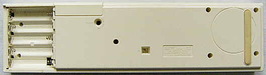
| removal of these screws voids warranty... | ||
 |
||
|
|