 |
 |
|
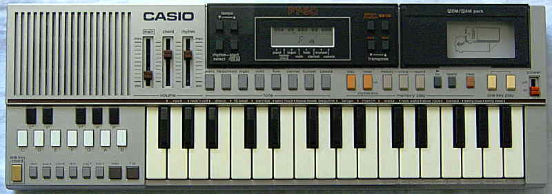
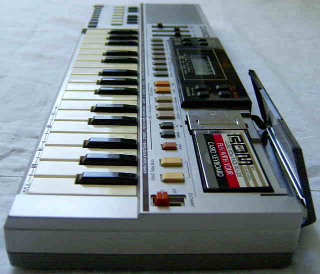
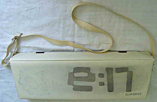
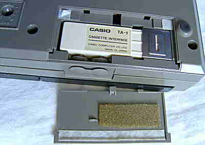
This instrument from 1983 was the only Casio keyboard with ROM-Pack slot but no key lighting; instead it can load the ROM-Pack musics into an internal sequencer, and with the optional Casio TA-1 module it can even save them on audio cassettes. Even a RAM-Pack cartridge Casio RA-1 was made for this thing to save sequencer data - I never saw any other Casio keyboard designed for using it.
|
|
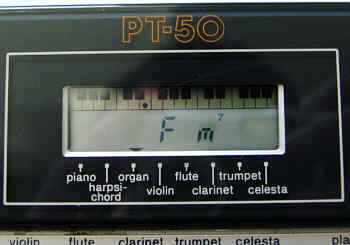
The PT-50 was seen (but not heard!) in the Gremlins movie from 1984; that movie scene replaced its tone with a thin plain squarewave beep (likely from a primitive piezo speaker toy keyboard or some kind of transistor tooter).
Due to general similarities I only describe here the differences to PT-30.
 |
 |
 |
 |
 |
 |
 |
 |
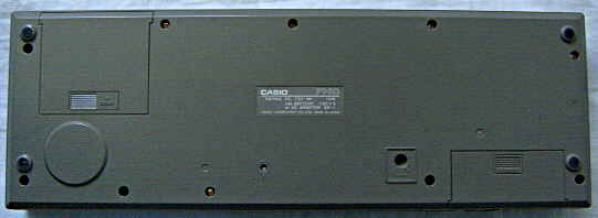
caution: The PT-50 may crash during battery insertion and not respond to controls anymore. If this happens, switch it on and press the tiny "P" (reset) button at the case bottom with a pointed object to clear memory (erases sequencer contents). To avoid the crash, if the instrument was left without batteries for over a minute (which corrupts SRAM contents) always slide the power switch into "on" position before inserting batteries or connecting a power supply.
Some preset sounds differ from Casio PT-30. The 'organ' here has neither vibrato nor sustain, the 'violin' and 'flute' here lack sustain also. The sounds 'horn', 'fantasy', 'mellow' of the PT-30 were replaced with "clarinet" (has no vibrato), 'trumpet' (like "horn" without sustain) and 'celesta' (like 'harpsichord' with sustain and 1 octave higher). Most stupid is that even the nice 'violin' multipulse (known from VL-1) has been replaced with a boring 7:1 squarewave.
The manual organ chord voice lacks here the dull organ bass component
and instead everything plays an octave lower, which sounds cheapish, because
the multipulse bass waveform of PT-30 was replaced with a simple 1:3 squarewave
bass that has no separate output pin anymore. But in opposite to PT-30,
here you can trill around on different chord type buttons while holding
a chord note key. (The PT-30 ignores further chord type button presses,
thus you have to also release and press again the chord note key before
you can choose another chord type, which was bad for comparing how different
chords sound.) With rhythm, the bass voice has here a low, sonorously buzzing,
decaying squarewave timbre with sustain, that resembles an e-bass but is
also a little brassy. The rhythms set is very different from PT-30 and
unfortunately lacks the nice arpeggio styles. But instead the rhythms now
have each a fill-in pattern with accompaniment. Annoying is that the rhythms
don't start immediately anymore after selecting them, but you have to press
the "start/ fill-in" button, which always begins with a 4 step snare lead-in
before starting the rhythm itself. Also the pattern restart trick of the
PT-30 can not be used here by the lack of "chord change" buttons.
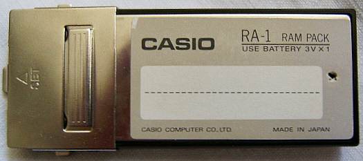
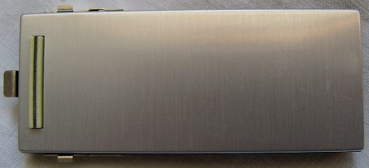
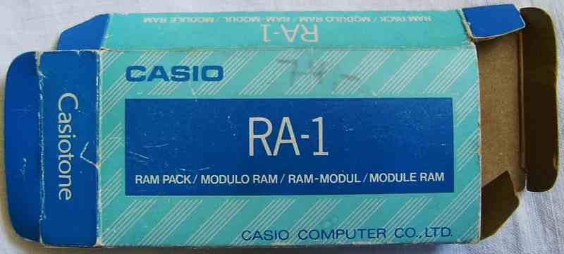
| Casio RAM-Pack RA-1
I finally found on eBay the mysterious RAM-Pack cartridge for the Casio PT-50. It is named Casio RA-1 and can store apparently only one song. You can even save any ROM-Pack song from the internal PT-50 sequencer memory to it, which is correctly loaded back including the obligato voice.
|
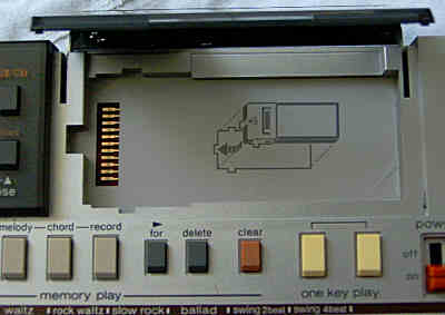
The ROM-Pack implementation of this keyboard is very different from all my other Casios and a little unobvious. To select a song, press the "R/MT" button once ("R" appears in the LCD), then type the 2 digit song number with the rightmost keys and press "play", which copies the song into the internal RAM (takes some seconds) and plays it. (Pressing "R/MT" twice displays "MT" and apparently tries to load the music file from a cassette through the optional Casio TA-1 module.) Unlike a ROM-Pack, the RAM-Pack RA-1 ignores the selected song number, because it apparently holds only 1 song. The "demonstration" button plays all musics from the inserted ROM-Pack in a sequence, starting with the first. The 2nd melody voice (obligato) of ROM-Pack musics plays a bit too quiet on my PT-50. (Warning: Playing any ROM-Pack musics overwrites and thus deletes the actual sequencer contents.)
Unfortunately I have no manual for this thing, but this is what I found
out. Press "chord" and then "play" to play only the chord track. Press
"melody" and then "play" to play only the main voice. To delete the sequencer
contents hold "record" and press "clear". To record your own melody into
the sequencer, hold "record" and press "melody" to enter melody recording
mode. Play the melody note by note (press "reset" to quit). Afterwards
the note lengths must be entered separately, and also chords can not be
recorded together with the melody. :-[ (No joke!
The PT-30 had no trouble with that.) To enter the note lengths,
press "play" in melody recording mode and step with the right tempo through
the melody using the "one key play" buttons until the melody ends (or press
"reset" to finish). When no note lengths are entered, the melody plays
with tremendous speed. To record chords works similar, but hold "record"
and press "chord" for the chord recording mode. To enter chord lengths
(not necessary when you played right), press play in this mode and step
forward with the "one key chord" button. To edit the sequencer contents,
enter the melody or chord recording mode again and step through your track
with the "for" button. Any new played notes or chords are inserted at the
current position. The "delete" button deletes the last played note/ chord
from the track. After edit press play in that recording mode and correct
the note lengths with the "one key play" and "one key chord" buttons again.
(Note: ROM-Pack musics contain beside melody and chord voice a 2nd
main voice called "obligato"; unlike melody and chord, this additional
voice can apparently not be edited in the sequencer.) To save the actual
sequencer contents on a RAM-Pack, press "R/MT" once and then "save".
 Like
the Casio PT-30, the PT-50 has an expansion cartridge slot for the
Casio
TA-1 tape memory interface to save the sequencer contents, thus
it might be possible to save with this thing ROM-Pack music data on cassettes
or upload them to a PC for further analysis or even sound emulation. Unfortunately
you can not play them through the RAM-Pack RA-1
on other ROM-Pack keyboards, because the RA-1 is incompatible with them. Like
the Casio PT-30, the PT-50 has an expansion cartridge slot for the
Casio
TA-1 tape memory interface to save the sequencer contents, thus
it might be possible to save with this thing ROM-Pack music data on cassettes
or upload them to a PC for further analysis or even sound emulation. Unfortunately
you can not play them through the RAM-Pack RA-1
on other ROM-Pack keyboards, because the RA-1 is incompatible with them. |
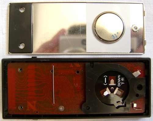
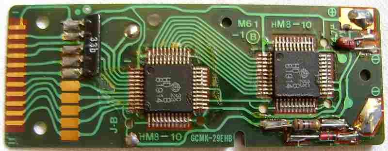
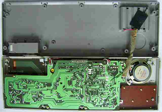
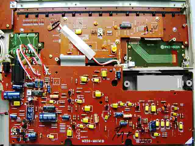
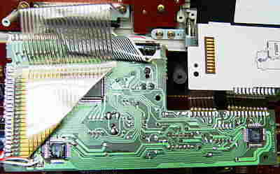
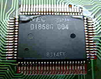
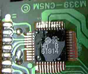
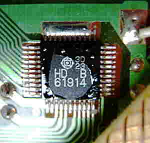
hardware detailsThe Casio PT-50 is built around the CPU "NEC D1868G 004" with 2 additional special SRAMs "Hitachi HD61914B". Like its predecessor PT-30 it employs plenty of additional analogue circuitry for percusion and main voice filtering.The instrument concept of the PT-50 (with ROM-Pack data format) is thoroughly described in the US patent 4624171 and (later) 33607. The internal data format of the sequencer differs between PT-30 and PT-50, so recordings saved on cassettes can not be exchanged. Despite many similarities, the software and many hardware details differ. The PT-50 service manual lists interesting differences to PT-30. So PT-50 has VDD -4.5V vs. -4V, 2 instead of 3 melody filters, bass & chord is common because of additional obligato circuit, clock frequency is 450 kHz instead of 600 kHz. The CPU is claimed to be"µPD1868G" instead of "µPD1868G-22" however my actual PT-50 has software number 004 while PT-30 has 001. The optional ROM-Pack could contain IC µPD-883G-B (RO-201), µPD-883G-E (RO-301) or µPD-883G-F (RO-302), which hints that PT-50 in different countries likely was shipped with different ROM-Pack. The small case is even more crowded than PT-30; between panel and analogue PCB it contains even a 3rd intermediate PCB as the digital mainboard. But fortunately this daughter board at least makes the CPU behaviour a bit easier to examine since you don't need to take out the panel PCB (with a hand full of loose buttons flying around) to access it. Also the LCD here is held by a sheet metal bracket that didn't exist in the PT-30, and the LCD segment layout (particularly chord letter segments) was changed.
The digital mainboard is a small daughterboard that contains the CPU, 2 SRAMs and a logic IC "Toshiba TC40H00P" (4x NOR) that is wired as 2x OR to switch 2 multiplexed bus pins on the ROM-Pack port, apparently to disable ROM-Pack during auto-power-off. rom pack pin 2 = pin 32 OR pin 73
This is the wiring of both SRAMs HD61914B.
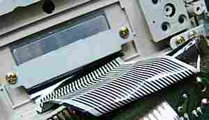
The +4.5V supply voltage for the CPU is weak and will make the pitch go down when loaded with additional components. The MT port for the digital cassette interface is wired like in PT-30. audio channels The individual sound channels and control lines are accessible on the rear grey 15 pin ribbon cable. It has pin 1 wired to CPU pin 21 (reset), and pins 2..15 wired to CPU pins 80..67 (white noise pin 72 through a 100k resistor). multipulse squarewave & timbre filter The main voice is based on the same multipulse squarewave sound synthesis like in its predecessor PT-30, but some preset sounds differ and sound less interesting. Likely to standardize the sound set for ROM-Pack support, e.g. the 'violin' waveform has been replaced with a boring 7:1 squarewave, 'mellow' (with strange tremolo envelope) became a 'celesta' and the bass voice was worsened and has no separate output pins anymore (those became the ROM-Pack obligato voice). The main voice is routed through 2 fixed timbre filters, those are controlled
by CPU outputs pins 68 O4 (highpass) and 67 O5 (lowpass) for 3 timbre settings
(both hi = unfiltered).
The accompaniment bass voice seems to be a 3:1 squarewave that is alternatingly output with the chord and muffled by a filter. In PT-30 it had a unique multipulse and own pins. The percussion works like in PT-30 and uses the same CPU pins. keyboard matrix
The input lines are active-high, i.e. react on +Vs. Any functions can
be triggered by a non- locking switch in series to a diode from one "out"
to one "in" pin.
A button wired at KC10->KI8 behaves like the regular 'start/ fill-in' button but keeps the rhythm fill-in running forever. To end the fill-in, press the 'start/ fill-in' button. pinout HD61914The "Hitachi HD61914 x" (44 pin SMD, pins count anticlockwise, x = a letter) is a 4 bit SRAM with built-in "self control circuit" that was used in Casio keyboards with D1868G CPU and programmable calculators (with CPU "Hitachi HD61913 xxx"). The "HD" and letter are printed above the "61914". Said letter can be absent, A, B or C; it is unknown whether it indicates the memory capacity or speed or other special functions (e.g. address decoding scheme); at least the version without letter has 1 KByte capacity (2048 words x 4 bit, seen in Radio Shack PC-4 service manual). According to PT-50 service manual, the HD61914B (also 1 KByte) differs from HD61914, so HD61914 can not be installed into PT-50 instead of HD61914B, but in PT-30 a HD61914B instead of HD61914 would work.Most important is that the first 11 pins have the same pinout like a ROM-Pack and so version B was also used in the special RAM-Pack RA-1 for Casio PT-50. In my 1st PT-30 the HD61914B seemed to have 3 additional pins 14, 17, 19 multiplexed with keyboard matrix and datasette port (likely NC to ease PCB layout). My 2nd (likely older) PT-30 contains a HD61914A (not B) and has an additional IC "TC40H000P" (4x NAND). In PT-50 both SRAMs are basically wired parallel. The only main difference seems pin 28 that is +Vs on the left IC but wired to pin 4 and cpu pin 30 (VDD2) on the right. SRAM pins 1..12 go to the cpu, while 24..27 and 29..33 are on +Vs. Although pins 34..44 are connected with various pins from 1..11 (see here), they are NC (confirmed by PT-50 service manual) and only used to simplify the PCB layout. But since VDD2 is only a standby signal, it may be that there is indeed a deeper meaning behind this (possibly decoded by some odd XOR tests). Pin 12 sends an interrupt to halt the CPU when autoplay has finished. Pins 13..23 are NC (confirmed by PT-50 service manual). Also in PT-30 3 SRAM pin traces are additionally wired to other pins (6 to 19, 7 to 17, 11 to 14), those are likely NC to ease wiring. SRAM pin 6 (clock phase?) is wired through a diode to CPU pin 28. In my 2nd PT-30 SRAM pin 6 is additionally wired through another diode to the output of a driver (2 chained NANDs) from CPU pin 30 and some RC network circuitry to to the power switch "off" contact (likely to prevent data corruption), which hints that SRAM pin 6 is always input. In PT-50 service manual is the RAM-Pack schematics with 2 SRAMs. The VDD2 line from ROM-Pack port is not only connected to both SRAM pin 4 but additionally to pin 25 (V4) of SRAM 1 and pin 28 (V1) of SRAM2, so they likely select the address range. The remaining pins of 24..33 are wired to pin 1 "GND". Pin 3 VDD1 is also the negative backup battery voltage from 3V button cell (with serial diode and 100 ohm resistor), which positive end is on pin 1. Pins 2, 4, 5, 6 have 1M pulldown resistors. It is unknown what pins 24..33 exactly do; in the pocket computer Radio Shack PC-4 (HD61914 with no letter) they are all wired to pin 1 and the optional RAM-Pack (pinout like a ROM-Pack) is simply wired parallel to the internal SRAM. That RAM-Pack (only empty PCB layout shown in service manual) apparently contains a single "HD61914 x" with pin 1 wired only to pin 33, pins 2 additionally to 23, pin 3 additionally to 22, pin 4 additionally to 28, pin 27 only to 29, connector pin 1 to IC pin 24. These additional pins likely map the address range for the 2nd RAM at $800h directly above RAM 1, which in the PC-4 starts at $200h above the CPU internal RAM. Additionally the traces to pins 3..11 are wired through 21..13, and pins 34..44 are all interconnected (likely NC to ease wiring). But by their wiring at least pins 22 and 23 seem to be not NC (contrary to their naming in PC-4 schematics). Also in RA-1, PT-30 and PT-50 there are many such connections, of those many pins may be NC to simplify the PCB layout. In the PC-4 the cassette interface port (to an 28 pin DIL IC HD43110 for data compression, 300 baud "Kansas City standard", serial data on D4) is wired parallel to the RAMs and only uses a different ø2 clock line from the CPU, which shows that Casio used this 4 bit bus in many places. This pinout was based on the service manual of the BASIC programmable pocket computer Radio Shack PC-4 (rebranded Casio PB-100) and the website of Piotr Piatek (thanks to him). The PB-100 was a crippled version of Casio FX-700P, which had an additional function button and the 2nd RAM already built-in (no RAM-Pack slot), marketed in 1982 as scientific calculator. Later I got the PT-50 service manual for verification. caution: The service manual indicates that this IC uses "negative
logic", i.e. technically +5V is its GND while 0V is its -5V supply voltage.
So the voltages are not was the pin names suggest. I use the positive
voltage naming convention (from 0V to +5V, not -5V to 0V).
According to Piotr's website the write command is $4 (OP=0), followed by a 4 bit device address, followed by the 11 bit address within the device (MSB is ignored). After this any amount of data can be written (in an OP=1 cycle), which makes the address counter advance after every 4 bit word. The read command is $0 and works similar. A single $0 word regularly appears on the bus when the calculator is idle, which may be a kind of soft reset. |
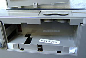
| removal of these screws voids warranty... | ||
 |
||
|
|