 |
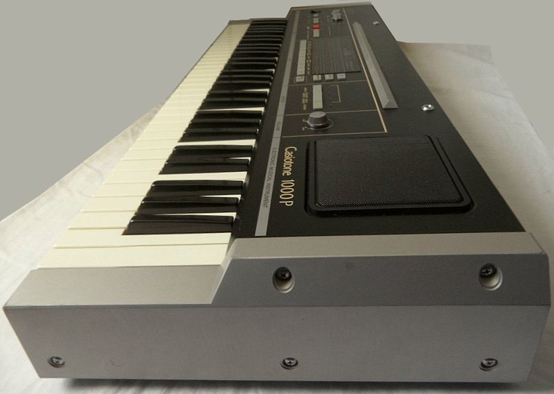 |
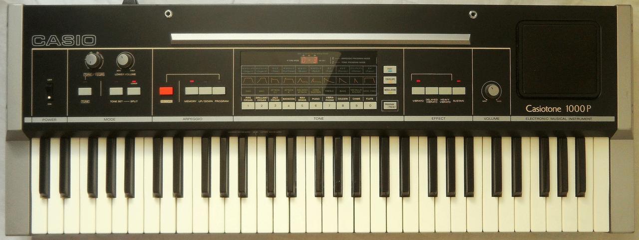
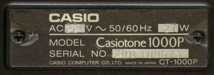
This instrument of 1982 was Casio's first fullsize synthesizer. It has additive synthesis and programmable arpeggiator but no rhythm.
|
|
 |
 |
 |
 |
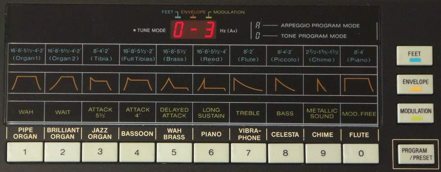
The instrument has 10 preset sounds and can store 10 user presets. To edit a sound, press "program/preset" to toggle to user preset mode. Then select its number by cipher buttons. Press the 'feet', 'envelope' and 'modulation' buttons (its digit will blink in display); you can type a cipher to change the corresponding synth parameter those are printed directly above them on the panel. Press that parameter button again to end blinking. This easy user interface concept resembles the "multi-menu" of Yamaha MK-100.
The sound generator was apparently optimized to simulate organ and flute tones, because everything else sounds very unnatural on it; the timbres are quite hollow, a bit harsh and bass notes tend to turn very dull. Likely it was intended as a direct competitor to the digital waveforms of the Yamaha PC-100 and should proudly demonstrate the end of the squarewave era, but since it sounds quite thin (very dull bass), it was no great success and thus later Casio keyboards (e.g. the great CT-410V) returned to stair- and squarewave based timbres.
All sounds consist of mixed combinations of up to 5 partials (layered sine waves) with different envelopes. While the preset volume "envelope" affects all of them equally, a 2nd kind of preset envelope named "modulation" changes the volume envelopes of (apparently up to 3) harmonics individually, e.g. to imitate a short filter sweep (wah effect) or increase bass or treble amount along the keyboard to approximate lowpass or highpass filtering. But no matter how exciting this additive synthesis thing looks in theory, in real life it sounds just like a sterile drawbar organ that lacks any grit and distortion because fake filters add no overtones. This sound engine is the absolute antithesis of POKEY - smooth and shiny and free of any rough intentional noise.
Arpeggio can be only used on the lower (chord section) keys. To program
the arpeggiator, press 'record' and 'program'. Type on cipher buttons the
note sequence; '0' is for rests. Sort your notes beginning from the lowest;
use the same number for playing the same note again. Press 'record' to
finish. Press 'program' to start the arpeggio and press chord section keys.
The 'memory' button keeps it running after key release. The entry knob
controls the tempo. The 'up/down' button selects the default preset arpeggio.
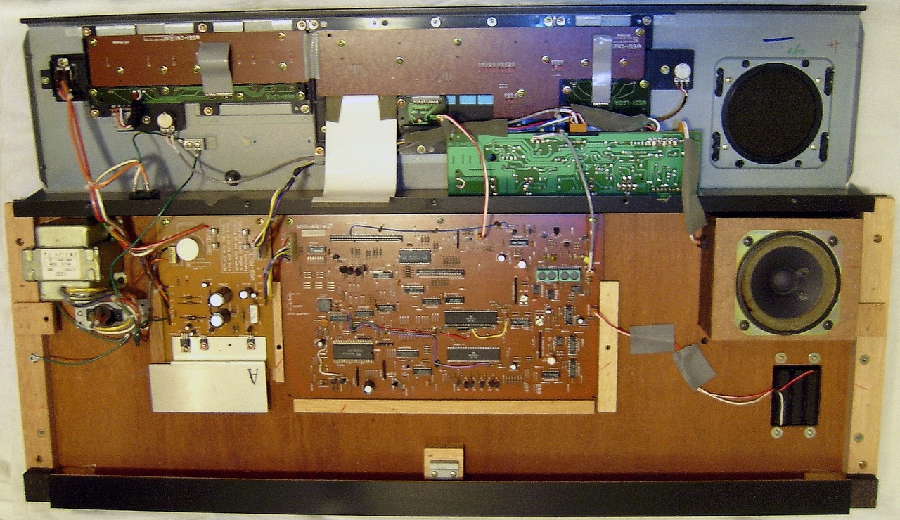
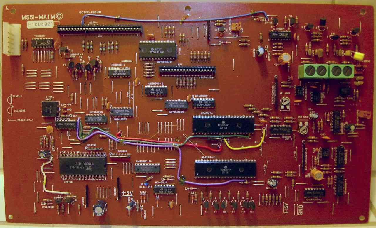
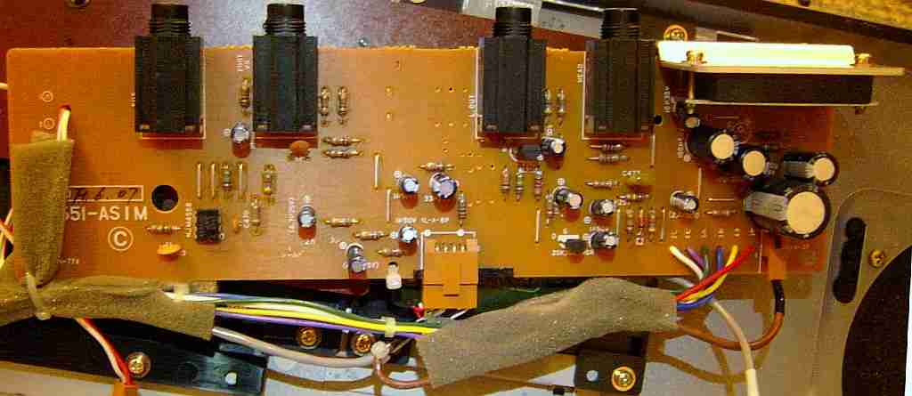
hardware detailsThe Casiotone 1000P is built around the CPU "NEC D7801G 077" that controls 2 sound ICs "Hitachi HD43517" and an SRAM "Hitachi HM4334P-3" (512 byte).
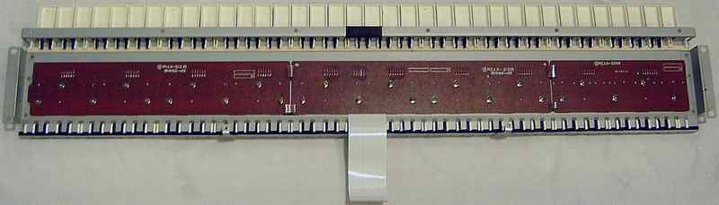
In keysplit mode each 4-note polyphonic sound IC uses its own DAC to separate melody and chord voice through own volume controls. But without keysplit, both ICs are daisychained in a way that sound IC B sends its digital sound data into sound IC A, which DAC outputs the 8-note polyphonic sound of both, while the DAC of B is muted. The bit compensation trimmers adjusts the DAC linearity. Edit a tone to synth parameters 876 with sustain and press a key. For upper keyboard (normal/melody) connect 2 channels of an oscilloscope to sound IC HD43517-1 pin 34 and op-amp 1 pin 1. Adjust trimmer VR1 to make it decay smoothly. For lower keyboard (chord section) select keysplit and do the same with test points at the 2nd sound IC and OP amp 3 with trimmer VR2. The sound IC is explained in the Casiotone 1000P patent (US patent 4538495) and further details in US patent 4453440, which describes digital envelope control by adding phase shifted copies of the same sine wave to avoid multiplication, and how overtones are produced by a kind of phase distortion predecessor. In this patent Casio also describes how to mix the outputs of multiple sound ICs digitally, which was never done in any other 1980th Casio keyboards I am aware of. Robin Whittle wrote (slightly desperate) in his technical bulletin "Modifying the Casiotone Instruments" from 1981 about this hardware family: "The Series III instruments are the CT-701, 601 and 501, the 1000p and the MT-70. [... They] use a Z-80 like microcomputer - and two or three identical 42 pin Hitachi chips to produce the sound. The computer scans the keys, organises everything, and talks to the Hitachi chips via an 8 bit data bus. The Hitachi chips produce 12 bits of digital audio with a 25 Khz sample rate and control an attenuator which follows the DAC. Each chip produces 4 waveforms which are composed of variable amounts of the first 8 harmonics, the levels of which can be changed in each channel in real time. It is impossible to make the computer run another program. Bypassing the lowpass filter gives a brighter tone, but adds to the already unacceptable noise level. I have had little success in getting rid of this noise - it seems to come from everywhere and therefore I cannot see much point in trying to do anything more with these instruments."When we compare that 25kHz mixing frequency and 12 bit with the 500kHz (see here) and up to 17 bit of the great D931C, it is no wonder that the HD43517 sound IC sucks. Like its competitor Yamaha PC-100 (and unlike previous Casios) the HD43517 sound engine has no switchable filters for different preset sounds anymore, which makes dull tones prone to digital noise and any static noise filter against it muffles bright tones more than desired. Apparently it was a crude attempt of imitating a Hammond organ or Yamaha's dull FM sound style, but it rather sounds cold, hollow and hissy and is way less versatile. It would be interesting to know how Z80-like the NEC D7802G (of Casio MT-70) really is. Whittle's above description is quite ambiguous; I am not really sure if he meant that each sound IC had per polyphony channel 4 drawbars of each a fixed waveform sample that (in the factory) was made from 8 premixed sine wave harmonics, or that each IC had 4 polyphony channels with each 8 sine wave drawbars. The US patent 4538495 reveals that none of these seem to be true, but genuinely the readout phase angle of a 12 bit sine wave ROM is multiplied with a periodic signal from a CPU controllable "harmonic control section", which appears to be a crude predecessor of phase distortion. Said section uses binary gate control signals {XS0, XS1, XQ, Y0, YS2, YQ} to selectively multiply the phase data and/or phase address with 2 or a previous sum and add the result to the sine wave readout address. Frequency- and phase data resolution is 20 bit. Instead of multiplying the output waveform with an ADSR envelope, it is added to the phase data of the sine wave ROM (US patent 4453440). The sound generation for the 4 polyphony channels is time multiplexed (summed at the end as a 12 bit DAC output value), so all register contents of the sound IC is stored in circular multi-bit shift registers. As a form of hardware multitasking, after processing each channel they cycle to the next entry. (The famous D931C sound IC functions similar.) The 7 bit envelope data shift register has instead of 4 even 20 stages, which means 5 cycles per polyphony channel, during those overtones are summed by switching the harmonic control section signals. The sound IC architecture suggests that the envelopes of all 5 harmonics may be programmed individually. But from my Casio 1000P behaviour I suspect that the harmonics have no independent envelopes but that every preset sound has only one envelope with few steps between those it crossfades the vector of harmonics (i.e. waveform), i.e. all overtones change in the same time slots which limits expressivity. keyboard matrixThis matrix is based on the Casiotone 1000P service manual. I haven't analyzed it by myself, so there may be still unknown eastereggs. The matrix outputs are decoded through a 74LS154 from CPU pins PE15..PE12 (1, 63, 62, 61). The inputs are pins PB0..PB5 (41..46).
The input lines are active-low, i.e. react on GND. Any functions can
be triggered by a non- locking switch in series to a diode from one "in"
to one "out" pin.
The data entry knob is a rotary encoder that toggles CPU pins PC2 and PC7. The LED matrix is wired from PA to PC pins. The PA pins are wired through a transistor array TD62302P. The display uses all PA-pins except PA5 wired to PC0..PC3. The panel LEDs are wired from the same PA pins to PC6, and from PA5 to PC0..PC3. pinout D7801G-077The "NEC D7801G 077" (64 pin zigzag DIL) is the CPU of Casiotone 1000P. It is likely the documented 8-bit microcontroller NEC 7801 with 4 KB ROM and 128 byte RAM. The NEC 7801 is 8080A bus compatible with alternate Z80-type register set and with 64 kByte address space. Its functions depend on the software of its internal ROM.The service manual tries hard to enshroud the inner working. It has
no CPU pinout but only schematics and mentions some individual pins, which
makes it hard to figure out their purpose.
pinout HD43517The Music LSI "Hitachi HD43517" (42 pin DIL) is a 4-note polyphonic sound IC based on additive synthesis, that became famous by the synthesizer Casiotone 1000P, but was also used in Casio MT-70, AT-40 and some fullsize woodgrain models. Each polyphony channel is mixing 5 harmonics (sine waves) with different digital envelopes in a similar manner like a drawbar organ. The IC outputs 12-bit digital audio to an external DAC and (like the later D933) 3 additional highest DAC bits control an external 3-bit expander circuit (sort of fast switching VCA, US patent 4414878) to increase dynamic range. (Without expander the DAC waveform tip looks sunken in like a collapsed copula and sounds distorted.) A sample & hold circuit then removes high frequency components. Interesting is that the IC can route its output as digital audio into another HD43517 for digital mixing through thats DAC to simplify analogue wiring. Unfortunately this wastes another DAC bit, and with only about 25kHz output frequency (due to the additional summing of 5 overtones per channel) the specs and tone quality are inferior to the earlier D931C. Interesting is that the internal signal processing (US patent 4453440) already resembles phase distortion, using phase-shifted sine wave addition from a 12-bit lookup table for fast multiplication. Frequency- and phase data resolution for each overtone is 20-bit, with 7-bit envelope controls.The external expander (aka D/A shift) circuit is active when more than
2 notes sound simultaneously. By bit combinations of the pins 37..35 it
switches 6 amplification levels.
Multiple HD43517 (up to 3?, existing in Casiotone 701) can be controlled by one CPU on the same 8 bit data bus. Normally each sound IC outputs audio through its own resistor ladder DAC, but in master-slave mode they can output through the DAC of the master (so e.g. the chord voice DAC can have different analogue post-processing and volume pot). For this the signals DAD (serial sound data), EVD (envelope data) and SYC (sync) are sent from slave to master sound IC. (The slave's DAC has to be muted externally - e.g. by its sample & hold stage.) DAD and EVD have to be disconnected to select normal mode. In MT-70 chip 1 is slave (MSO pin grounded) but DAD/EVD are disconnected. On chip 2 DAD/EVD have a 47k pullup resistor, hence MT-70 does not use the digital audio connection at all. Only SYNC interconnects both. In Casiotone 1000P the Melody LSI (chip A) is master and Accomp LSI (chip B) is slave; data flows from slave to master. A grounded MSO pin sets slave mode and so seems to control data flow direction on DAD/EVD. According to the Textbook, in Casiotone 701 chip A and B are connected to an own DAC while chip C uses serial digital audio to send its sound (bass and accompaniment) only to the others. With chord or accompaniment switch on, the DAD/EVD lines get disconnected (through a 4066?) to let the Melody LSI output only its own 4 channels, while in melody-only mode DAD/EVD are enabled to route all 12 channels through the DAC of chip A. This pinout and description is based on the Casiotone 1000P service
manual with its handwritten schematics (had incomplete numberings) and
the "Textbook Casiotone 701 601" (service manual). Apparently all "O-#"
pins are outputs, "I-#" are inputs and "IO-#" can be both.
The address space of each sound IC is set by wiring of pin 18. It is unknown how the 3rd sound IC in Casiotone 701 is distinguished. |
The only earlier Casio synthesizer was the VL-Tone
1. Other synth-like early Casios were the great CT-410V
and (hardware see there) MT-65. The latter is technically not a
synth but has many sound variation switches for synth-like operation.
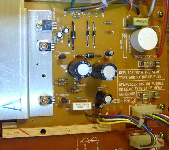
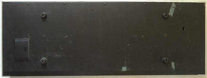
| removal of these screws voids warranty... | ||
 |
||
|
|