This rare keyboard of 1983 (service manual date) has semi-analogue percussion and a complex multi-track sequencer with LCD and datasette storage. Key features of this heavy 61 keys model was the "sound locator", that permits many different stereo panning effects.
The main voice is based on the consonant-vowel sound engine of MT-65 (see CT-410V) upgraded with 2 sound ICs, but Casio wasted a complex hardware for a rather unimpressive instrument that missed the chance of sounding interesting.
The CT-7000 with its strange effect engine was a child of the stereophony hype. In an era when HiFi sets with tower speakers became desirable and popular, soon every cheapish radio and ghettoblaster was expected to have 2 speakers and boast with some kind of spatial effects. Everythings summitted into Dolby Surround that filled living rooms with copy protected audio through digital cables of up to 8 speakers, until technology degenerated into often a single bluetooth speaker for streaming junk music in mono wireless from smartphones those are now destroying people's brains.
 |
 |
 |
 |
 |
 |
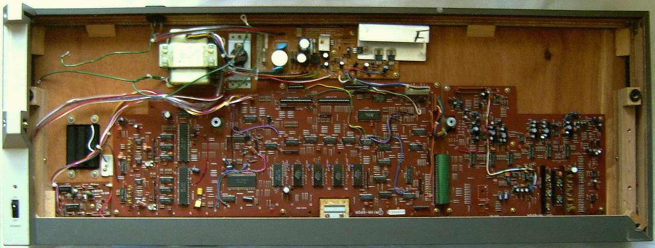
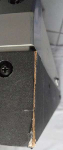 The
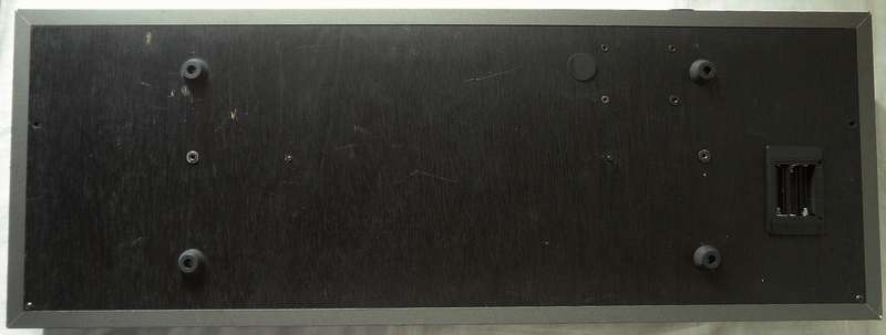
large wooden case with metal parts makes this instrument 12.5kg heavy,
but is veneered with a flimsy kind of cardboard coated with Casio's dread
grey wallpaper that scratches, flakes and chips off by any rough handling
and so spoils stage use. The sequencer memory runs on 3 AA batteries, but
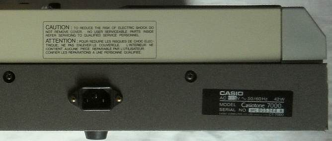
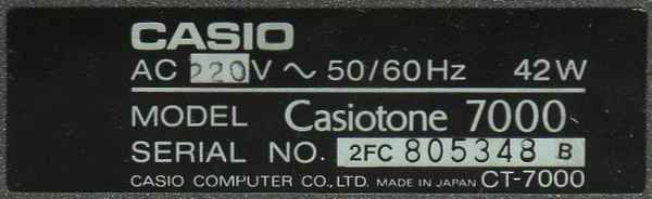
the according to its type plate hefty 42W consuming instrument can't. Would
the beefy 2x 8W power amp contribute to this, despite common 2x 2W with
efficient speakers would have done the job as well? I worried of chip overheat
by lack of heatsinks in that closed box, knowing how much cooling effort
is needed in modern laptops. A socket power meter revealed something different;
depending on cranking up volume it only draws 15 to 17W. WTF?! Unless they
measured a power-on inrush current during milliseconds of charging its
PSU capacitor, Casio obviously fooled customers, those in an era before
efficiency regulations considered things those draw no watts powerless,
and even the annoying case construction may have targeted granny thinking
of "if it has no wood, it can't sound good". Actually the somewhat bassless
speakers sound (despite big magnet) neither exceptionally great nor very
loud (not remotely like 2x 8W). E.g. my HT-6000
of 1987 is as loud and rated 7.7W (on batteries), so for early 1980th complex
multi-chip hardware with iron core trafo and stereo amp 17W is plausible
and 42W false advertising.
The
large wooden case with metal parts makes this instrument 12.5kg heavy,
but is veneered with a flimsy kind of cardboard coated with Casio's dread
grey wallpaper that scratches, flakes and chips off by any rough handling
and so spoils stage use. The sequencer memory runs on 3 AA batteries, but
the according to its type plate hefty 42W consuming instrument can't. Would
the beefy 2x 8W power amp contribute to this, despite common 2x 2W with
efficient speakers would have done the job as well? I worried of chip overheat
by lack of heatsinks in that closed box, knowing how much cooling effort
is needed in modern laptops. A socket power meter revealed something different;
depending on cranking up volume it only draws 15 to 17W. WTF?! Unless they
measured a power-on inrush current during milliseconds of charging its
PSU capacitor, Casio obviously fooled customers, those in an era before
efficiency regulations considered things those draw no watts powerless,
and even the annoying case construction may have targeted granny thinking
of "if it has no wood, it can't sound good". Actually the somewhat bassless
speakers sound (despite big magnet) neither exceptionally great nor very
loud (not remotely like 2x 8W). E.g. my HT-6000
of 1987 is as loud and rated 7.7W (on batteries), so for early 1980th complex
multi-chip hardware with iron core trafo and stereo amp 17W is plausible
and 42W false advertising.
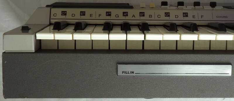 The
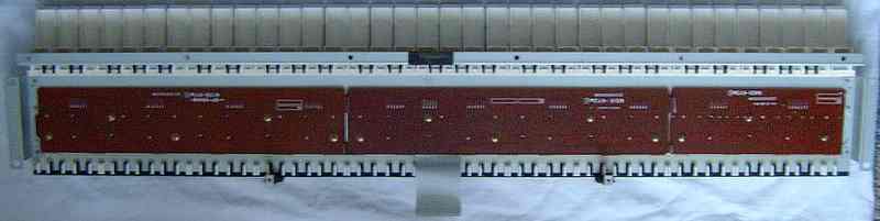
Casiotone 7000 is nothing fantastic but full of strange quirks. So a crazy
gimmick is the rhythm fill-in trigger in form of a metal touch sensor bar
under the front rim along the chord section keys. This feels more like
something circuitbent than a commercial keyboard (however some 1970th keyboards
had a button for 7th chords placed there). But it acts only like one button.
Casio missed the chance of placing here something analogue like a ribbon
controller or distance sensor for pitchbend or VCF to do something really
avantgardistic. But in 1983 people were still intrigued by touch keys like
they were magic from future (I have a calculator with such power button),
so Casio may have considered this novelty a sales argument worth to spend
additional circuitry. To make it clear, this keyboard is not terrible,
but it hasn't aged well.
The
Casiotone 7000 is nothing fantastic but full of strange quirks. So a crazy
gimmick is the rhythm fill-in trigger in form of a metal touch sensor bar
under the front rim along the chord section keys. This feels more like
something circuitbent than a commercial keyboard (however some 1970th keyboards
had a button for 7th chords placed there). But it acts only like one button.
Casio missed the chance of placing here something analogue like a ribbon
controller or distance sensor for pitchbend or VCF to do something really
avantgardistic. But in 1983 people were still intrigued by touch keys like
they were magic from future (I have a calculator with such power button),
so Casio may have considered this novelty a sales argument worth to spend
additional circuitry. To make it clear, this keyboard is not terrible,
but it hasn't aged well.
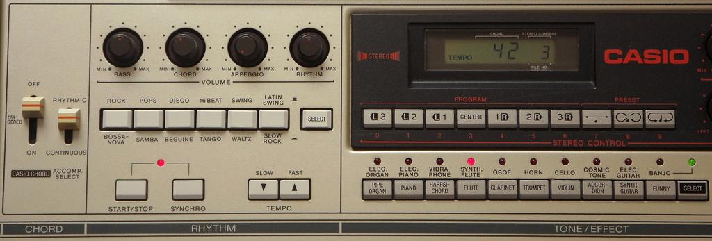
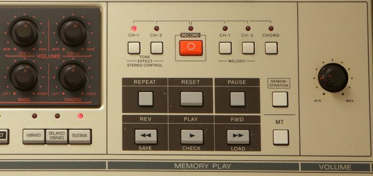
The "sound locator" is not the typical stereo chorus found in other Casio keyboards, but a digitally controlled panning effect. With a row of 10 OBS buttons, the main voice can be swittched to one of 7 positions or 3 moving patterns at the speed of the tempo control. They are fast toggle between both sides and 2 speeds of gradually panning. But also the moving patterns only step and not glide continuously, which makes them sound dry and choppy. The classic Casio stereo chorus would have been nicer. But obviously this keyboard was meant as a novelty, that (like Casiotone 1000P) was mainly intended to just sound "different", no matter how.
The main voice and percussion resemble Casio MT-65 but lacks the many sound variations of the latter but only supports delayed vibrato. Also accompaniment is simpler, but at least rhythm can be used with manual chord ("continuous") mode which always holds notes (chord memory), and it has arpeggio.
The manual proudly boasts: "Dual Keyboard Function - By using the effect memory with manual play, you can change the sound, effect, sound location and volume of the melody with a press of a button. It's as though there were two keyboards in one..." But this is less exciting than it sounds. Despite the instrument contains 2 copies of the entire main voice sound hardware (sound-IC with filter and analogue parts), preset sounds can neither be split nor layered on keys. but only in the sequencer. By hand you can only play one of 2 registrations. For this press "tone effect CH-1", select the 1st preset sound, press "tone effect CH2" and select the 2nd preset sound. Their ratio can be varied with the CH1 and CH2 volume knobs. The tone effect buttons so can quickly switch between these 2 registrations (including vibrato, sustain, pan mode etc.) but not place them simultaneously on the keys.
The demo song is a medley of short classical music pieces that is nicely
arranged as symphonic rock- an at its time popular style that was promoted
by bands like Ekseption and Rondo Veneziano.
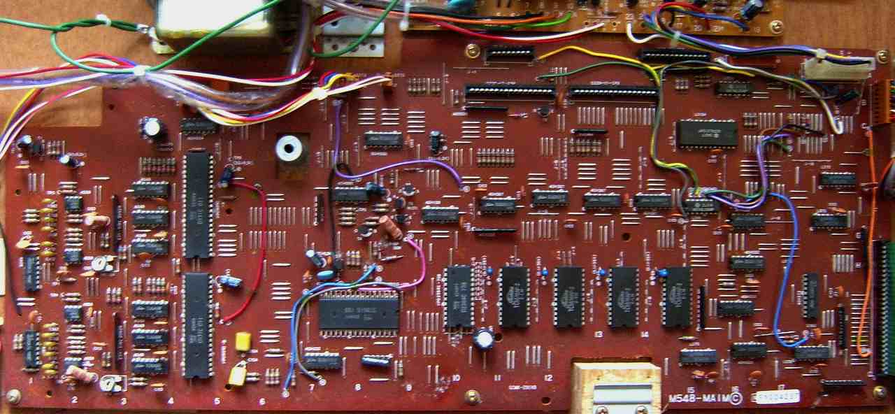
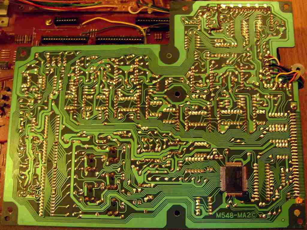
hardware detailsThe Casiotone 7000 is built from MT-65 hardware (see CT-410V) with an accompaniment CPU D930G 011 and here 2x sound IC D931C. Very unusual is that everything is here controlled by an additional CPU D7801G 109 (crystal clocked @4MHz), which was likely done to support 61 keys those the D930G standard version 011 can not handle.
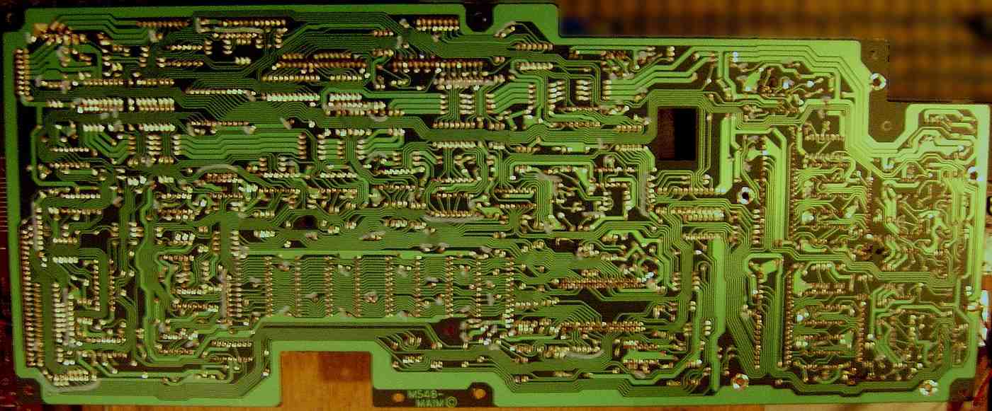
I didn't get far and soon gave up with analyzing this complicated hardware. Eventually I got the Casiotone 7000 service manual that helped to understand the general architecture, although it does not explain details, so they still may be wrong. It refers the main CPU software number as 019, while my actual keyboard has 109. This main CPU uPD7801G handles the keyboard matrix, MT (datasette) port and digital panpots, controls the 2 main voice sound ICs D931C and the accompaniment CPU D930G 11 which outputs chord voices and controls the semi- analogue percussion. The main CPU uses an external 8KB ROM "NEC D2364C 739" (I dumped it). The data bus is muxed with keys, panel switches and input gate. main CPU memory map:
The main CPU controls the D930G 11 apparently by simulating keyboard matrix inputs (which hints that there is no secret internal protocol). For this the CPU does not read its matrix outputs (KC1..KC10 are not used) but syncs with it and sends signals to the KI pins. Strange is that D930G pin 31 is wired hi through an 1k resistor, which may inform it about the absent sound IC or even change the data format for being controlled by an external CPU. (Casio Symphonytron RC-1 with similar configuration does this too.) This looks like a model select feature, and the 1k resistor hints that pin 31 can also act as output. The CPU data bus is latched through flipflops clocked by address line A3 during I/O access. (Logic gates are wired to CPU pins A3, IO /M and /WR to implement function "OR(NAND(A3,PC5),/WR)" The same logic is used in many places to select things by other address lines.) PA7 (RES) -> I1 (SCH)
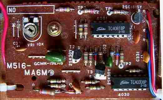
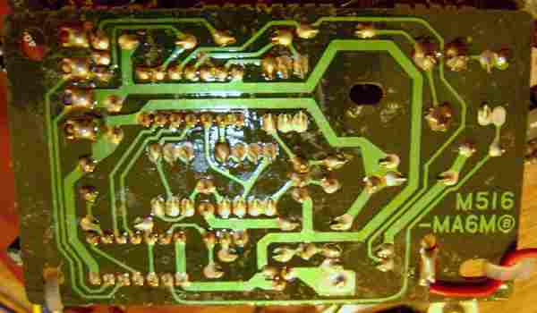
The text explains: "Microcomputer (uPD7801G) waits for endless loop unless it receives RB (receive busy) and KRE (key receive enable) from uPD930G." But the main schematics is a huge and puzzeling grid of demuxed bus lines full of renamed connections that looks like staring into a loom or the blueprint of AMDs Infinity Fabric. Also the semi-analogue percussion is driven by the D930G, employing
the same 3 hybrid modules like Casio MT-800. This is what Casio considers
the official decay settings (fall time down to 50% of initial level).
The entire main voice sound hardware exists twice to handle the 2 melody channels for the sequencer. The CPU controls both D931C through PA3..PA0 = DB4..DB1
Both CE signals for selecting the D931C are latched through a flipflop(?) driven by CPU pins PC0, PC1. The SCH (reset) pins are latched from CPU data bus through a flipflop clocked by address line A2 during I/O access. The text explains: "A Schmitt signal is generated every time a tone is changed." ("Schmitt" (-trigger) was one of those arcane names for reset.) The D931C sound ICs here have no connection to the D930G, hence the
preset sound set partially differs from MT-65 because sound data comes
from the main CPU. But also here each sound IC D931C uses its outputs IO-1..IO-3
to set its own fixed filters ("X" = hi).
The digital pan pots for stereo effects are controlled by the main CPU. Each uses 3-bit for the 7 positions. Pins PB0..PB2 control position of melody channel CH1, PB3..PB5 control position of CH2. The arpeggio and rhythm position is controlled by a flipflop at the data bus clocked by address line A4 during I/O access. The rhythm panpot is specially wired in a way that normal rhythm is panned to the center, but during fill-ins the individual percussion sounds get each a different position in the stereo panorama. The MT interface of the cassette port is driven by main CPU pin PA6 (out) and PC6 (in). It transmits average 1600 baud by one wave Kansas City standard and supports file names and error checking. keyboard matrixThe keyboard matrix is handled by the main CPU. This matrix is based on the Casio CT-7000 service manual. I haven't analyzed it by myself, so there may be still unknown eastereggs. It explains no details how the CPU reads and writes the matrix. Apparently the KC# pins are written to a decoder on the data bus during a pulse on A2. The KI# lines are read through data bus during a pulse on A0.
The control panel is in a separate matrix. Apparently the SC# pins are
written to a decoder on the data bus during a pulse on A2. The SI# lines
are read through data bus by a pulse on A1.
The input lines are active-low, i.e. react on GND. Any functions can
be triggered by a non- locking switch in series to a diode from one "in"
to one "out" pin.
The panel LED matrix uses the pins BD0..BD7 to LA, LB, LC. They are written by CPU pins A5..A7 during a pulse on A14. LED flashing is controlled by an oscillator that feeds the /INT1 pin. pinout D7801G-109The "NEC D7801G xxx" (64 pin zigzag DIL, xxx = software number of internal ROM) is the main CPU of Casiotone 7000. It is likely the documented 8-bit microcontroller NEC 7801 with 4 KB ROM and 128 byte RAM. The software number in my keyboard is "109", but the service manual lists it as "019" and does not contain an annoted pinout but only pin names in schematics.The NEC 7801 is 8080A bus compatible with alternate Z80-type register
set and with 64 kByte address space it would have been powerful enough
to run a contemporary 8-bit homecomputer. Some pin names differ from NEC
7801datasheet (port PE# became address bus) but pinout and memory map look
plausible.
Pin 20 "IO /M" becomes lo during memory access to switch the bus between memory and I/O. |
A much better keyboard with similar case was Casio
CT-6000. With midi, velocity sensitive keys with aftertouch and
pitchbend it was a definitely much more serious instrument and as a Casio
far beyond its time.
| removal of these screws voids warranty... | ||
 |
||
|
|