|
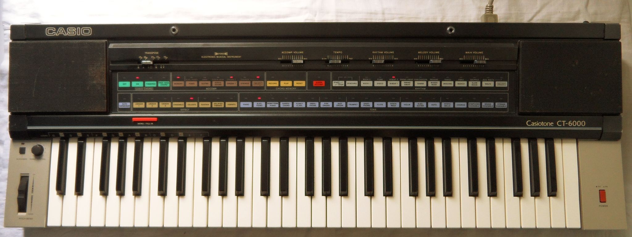
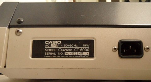
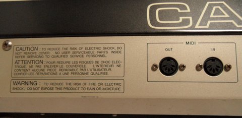
This visionary instrument of 1984 (service manual date) was Casio's first midi keyboard. This is one of their most important milestones, because it was not only velocity sensitive but even has (monophonic) aftertouch, pitchbend and the unique "Super Accompaniment" that responds to velocity and chord progression.
The timbres of this flagship are somewhat special. Forum people had mused if it secretly introduced phase distortion before there were CZ-synths. But technically it is a variant of Consonant-Vowel, that can layer any 2 preset sounds with others or in several forms with itself (for chorus-like effects). Also the percussion hardware is completely unique and may be the most sophisticated kind of blip percussion. It also has auto-harmonize and a simple chord sequencer. This special hardware is almost one of a kind; only one lesser capable keyboard and a few e-pianos later were based on it.
 |
 |
 |
 |
 |
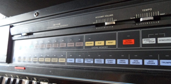
The Super Accompaniment has complex behaviour, but unfortunately lacks arpeggio. This is no synth, but the instrument can layer 2 preset sounds with the tone mix button. The effect "unison" layers a sound with itself, which reduces polyphony (1 = 4 notes, 2 and 3 only 2 notes). The effects "ensemble" and "celeste" add a chorus effect and are also part of some preset sounds.
Unfortunately the preset sounds have stubborn preprogrammed controls
those may sound natural but reduce capabilities. So all decaying sound
except 'synth bells' ignore key pressure, 'pipe organ' ignores velocity
and pressure, and 'synth bells' has always active sustain.
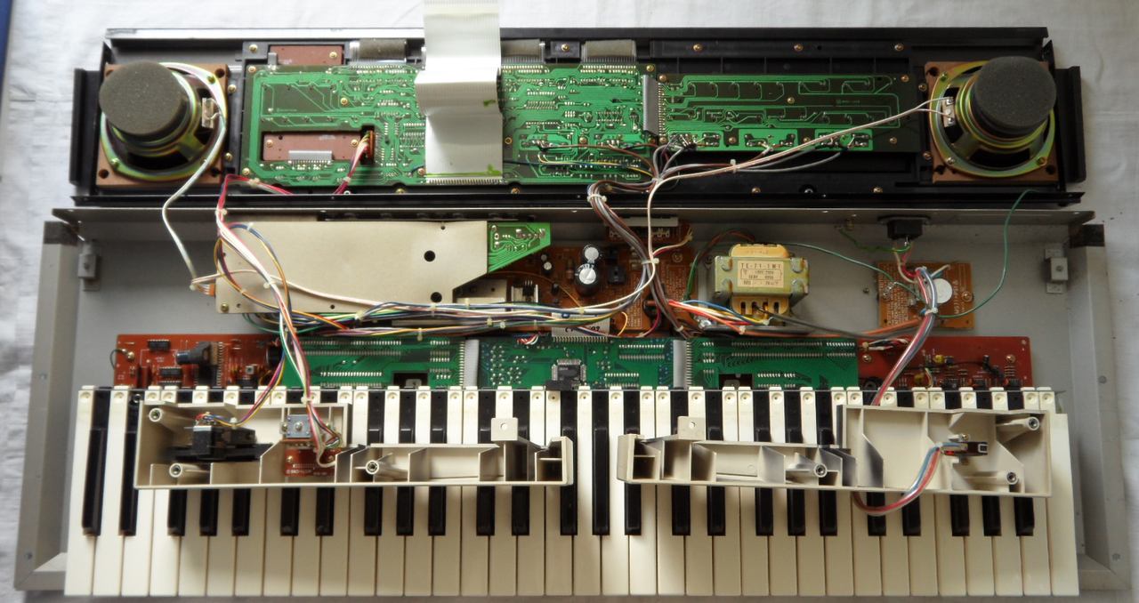
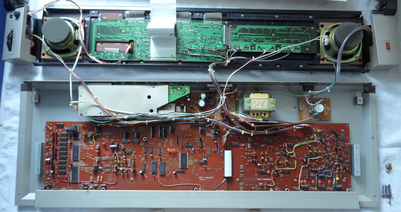
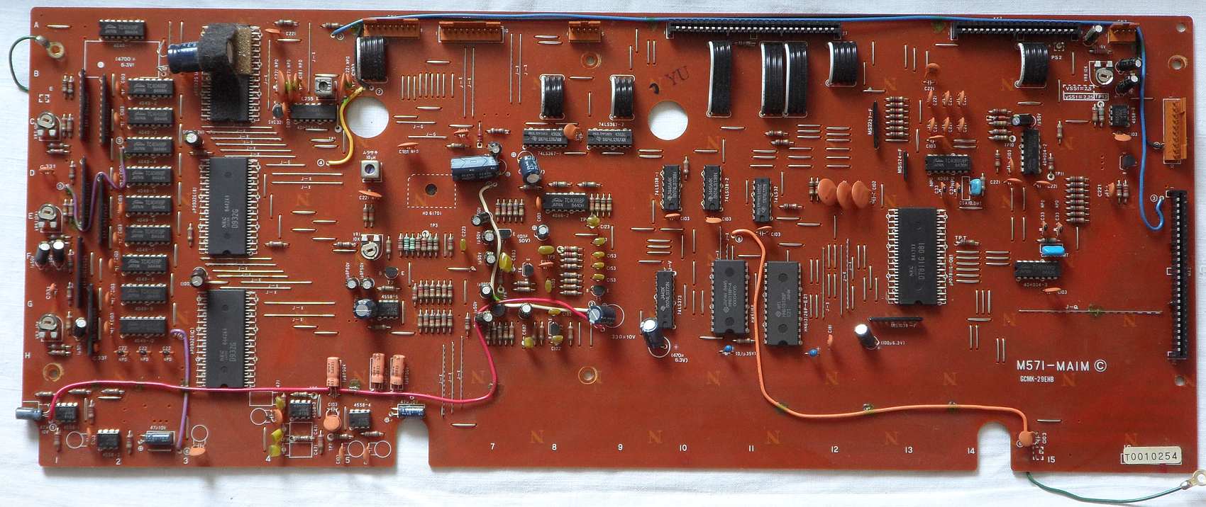
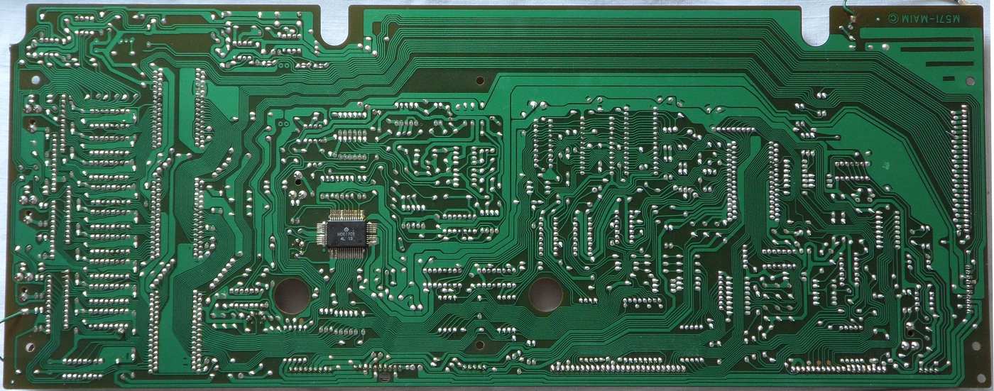
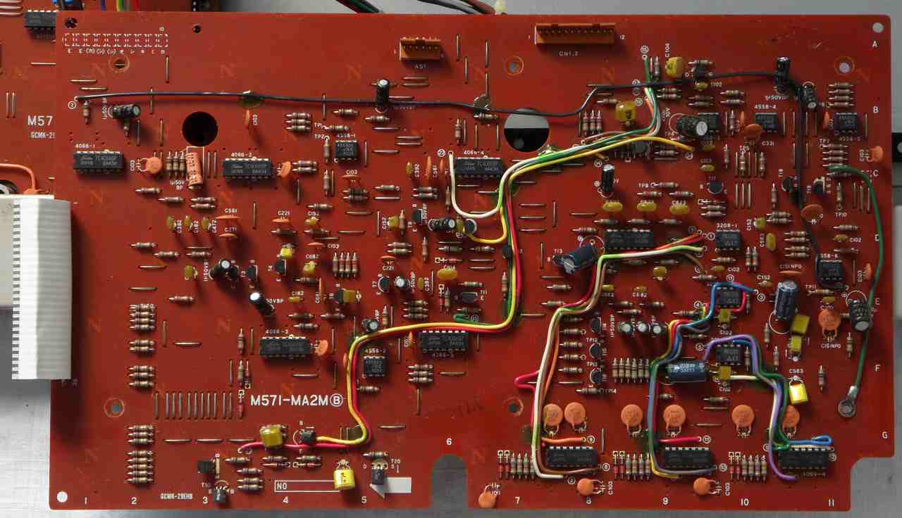
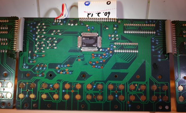
hardware detailsThe Casio CT-6000 is built around the CPU "NEC D7811G 081" that controls 3x sound IC NEC D932G, the percussion IC Hitachi HD61701 and key velocity IC OKI M6200.
This hardware analysis is based on the service manuals of Casio CT-6000 and CPS-201. Despite showing various details, the CT-6000 service manual tries hard to enshroud how the instrument works in whole and gets controlled by its software. So pins and ports get renamed from page to page, and connections of address decoders and audio routing is hard to track and overview. The 3 sound ICs D932G have digital output pins to switch fixed lowpass filters, gain, mute and stereo chorus. The audio bits from each sound IC are routed through a driver and then 2 resistor ladder DAC hybrids "S19Z2052R". Like in classic Consonant-Vowel synthesis, each preset sound is mixed here from multiple sound ICs those each output a subvoice with different external filter. "Pass" means the signal bypasses a filter unfiltered. "off" means it gets muted. They are switched by the corresponding O# pins (I.a. "A23" = output O23 of sound IC A, no address line). sound IC A filter {A25=LPF 1 kHz (T2), A24=LPF 5 kHz (T3), A23=pass}
The original table in the service manual is hard to overview. I redesigned
it a bit and added pin numbers. The O## are the control output pins of
the corresponding sound IC. "X" = hi (enabled).
With chord or accompaniment, the 3rd sound IC is removed from the melody
voice (so disabling a subvoice) and routed to a separate channel to play
the chord voice. It is switched by CPU pin 21.
During switching of preset sounds, the CPU mutes sound output by pulling
pin PC5 lo to avoid popping noises. To adapt the volume of subvoices, there
are 3 gain controllers. Gain controller 1: when switch A26 (O26 of sound
IC A) is off, melody A and B volume ratio is 1:1, else 2:1. Gain controller
2 affects the volume of melody C; switches C25, C24 (O25, O24 of sound
IC C) varies it in 4 steps (resistance 100k, 50k, 33k, 25k). Gain controller
3: switches A28, A27 (O28, O27 of sound IC A) set ratio of melody A+B relative
to C the same way in 4 steps (1:1 to 4:1).
Sustain and delayed vibrato need no external circuits,
but are listed in the service manual.
The stereo chorus is more complex than in average Casio keyboards. It uses 3 BBD ICs MN3209 with 120° phase shifted clocks for better stereo effect. The audio of each line goes through pre-emphasizer, front filter, BBD, rear filter, de-emphasizer, mixer. 3 VCOs generate clock pulses for the BBD. The three-phase LFO1 generates 120ms triangular wave when "ensemble" is turned on. Three-phase LFO2 generates always 1.5s triangular wave when power is on. LFO1 and LFO2 are mixed 1:10. An LFO2 controller circuit jumpstarts LFO2 by power-on and stops by power-off, because else it would not oscillate properly. The stereo chorus is controlled by outputs O21 and O22 of sound IC B. In CT-6000 schematics page 1 the LS32 input pins 12, 9 and 4 are only connected to ROM pin A8, A9 and A10. Because these are all inputs, it looks like a drawing bug (3 missing dots) because CPU A8, A9 and A10 need connection to these ROM pins too. A12..A14 decoder LS138 outputs is chip select for 3x D932G, HD61702 and the RAM. CEH HD61701/CE = /(/A14 * /A13 * A12)
The service manual tells, ROM is selected when A15=lo. RAM is selected when A15=hi but A13, A14, A15=lo. ROM = 0XXX XXXX XXXX XXXX
I expect that only one sound IC D932 is addressed at a time, so the X at A10..A8 need to be 1 to prevent collisions. But the addressing is dirty with plenty of mirroring. Of the 16KB ROM only the 2nd mirror is complete if the lower part is masked by the CPU internal ROM. CPU memory map:
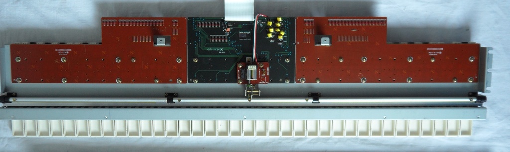
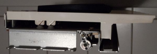
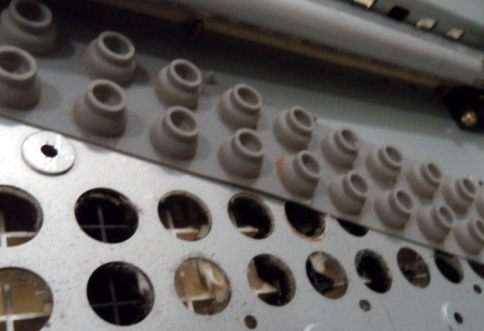
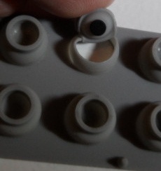
Coil L255 (D932G clock frequency) is the tuning preset; with tuning knob centered, key A3 shall be 442Hz. The HD61702 percussion IC oscillator frequency 4.9468 MHz is adjusted by a 10uH. The voltage VDD of the M6200 is 5.5V. Connect a voltmeter to checkpoint TP12. Adjust VR8 so that VSS = (VDD*2.55/5) volts. The D932G bit compensation trimmers tweak the lower bits so that waveforms decay symmetrically (visible on oscilloscope). keyboard matrixBecause the keyboard is velocity sensitive, it uses 2 rows of contacts to precisely measure the timing interval between upper and lower contact when they close. The CPU controls the key touch controller IC M6200, which contains RC circuits and 5-bit DAC. The KI# inputs here are analogue to sense the mixed signal of both contacts from a key (KC#A and KC#B) simultaneously.
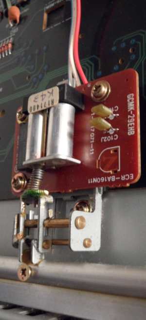
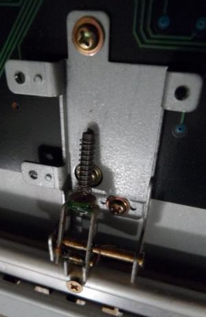
The monophonic aftertouch is a sensed by a tilting mechanism under the keybed that pushes a core into a coil that varies the frequency of an oscillator connected to M6200 pin AP2. The frequency needs to be 990 +/-30kHz idle and reduce to 85 to 250 kHz when a key is held down with 1.2kg force. The panel matrix is controlled by the CPU. The outputs C0..C11 are demuxed
through a SN74154N from CPU pins 1..4 (LB0..LB3). The inputs KI1..KI6 are
inverted CPU pins 9..15 PB0..PB6). The bender range is set by a 12-position
rotary switch, which 4-bit gray code(?) combinations are read through the
panel matrix. Also the transposer slide switch is connected here.
The input lines are active-low, i.e. react on GND. Any functions can
be triggered by a non- locking switch in series to a diode from one "in"
to one "out" pin.
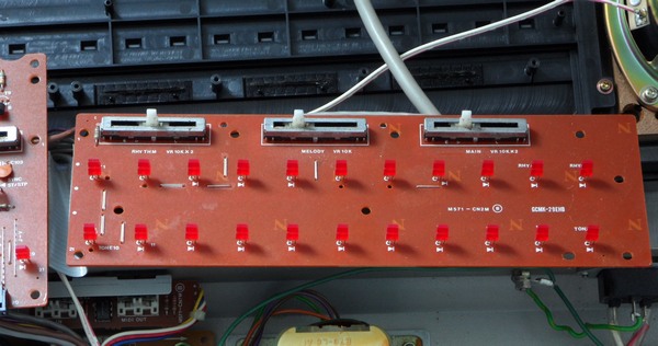
In LED matrix is driven through latches from data bus BD0..BD7 latched by a pulse on LE0..LE3 (those are decoded by LS138-1 from A0..A2 latched in LS373 by a pulse on ALE). Preset sounds are lit by LB0..LB3 through a decoder against LB4..LB5. LB7, LB6 to GND is "synchro" red/green. pinout M6200The Key Touch Control LSI "OKI M6200" (100 pin SMD) handles the keyboard velocity sensing in Casio keyboards like CT-6000, HT-6000 and FZ-1. It contains RC circuits and 5-bit DAC to measure the time difference between 2 contacts closing under each key. It is designed to be controlled by an external CPU. It need 8 external capacitors (100nF) and resistors (150k) to sense up to 8 simultaneous keypresses.This pinout is based on service manuals of Casio CT-6000, HT-6000 and
FZ-1.
The wiring of pins 33 and 12..15 look strange and may be test pins. The CT-6000 service manual tells that pin 33 is wired hi or lo to select the CPU type (lo=D7801, hi= D7811). Most Casio service manuals keep silence about such things. pinout D7811G 081The CPU "NEC D7811G xxx" (64 pin zigzag DIL, xxx = software number of internal ROM) was used in many early or professional 1980th Casio instruments. NEC D7811 is a generic microcontroller with internal 4KB ROM, 256 byte RAM and 8 analogue inputs (8 bit ADC).This is the pin meaning of software number 081 that is used in Casio
CT-6000.
pinout D932GThe Music LSI "NEC D932G" (64 pin zigzag DIL) is an 8-note polyphonic sound IC with digital envelope for velocity sensitive keyboards, that was used in Casio CT-6000, CPS-201 and some e-pianos. It supports 17-bit digital audio output (pin O1..O17 for use with resistor ladder DAC). Not much is known about this IC, beside that it was a direct successor of D931C and based on similar technology. So it has e.g. outputs to switch things like fixed timbre filters. The data input from CPU is here 8-bit wide, but only 4-bit in the opposite direction.The D932G seems to be the missing link in Consonant-Vowel technology
between D931C (programmable waveform and envelope) and D935G
("Spectrum-Dynamics" synthesis with complex modulation envelopes and VCF
control); like the latter it supports velocity and pitchbend, but still
uses fixed analogue filters and behaves a little grainy. (D933G was Phase
Distortion, which controls no filters and is not related).
Unlike D931C, the meaning of each control pin is far less standardized.
So the 3 sound ICs in CT-6000 use them differently.
The CPS-201 has only 2x D932G and its control pin assignment differs. Also the basic e-piano CPS-101 was claimed to employ D932G. But generally the use of D932G was rather shortlived; it got soon replaced with D933G (Phase Distortion) and D935G (Spectrum Dynamics). pinout HD61701The Rhythm Generator "Hitachi HD61701" (54 pin SMD) is the percussion IC of Casio CT-6000, CT-6500 and CPS-201. This chip is a mystery, since it was used nowhere else, and it doesn't seem to be sample based. Instead it seems to be the last and most sophisticated generation of blip percussion, that uses basic waveforms and shiftregister noises to synthesize sounds. So the instrument generates 23 different drumkit sounds from a tiny chip that certainly had not enough ROM for sample playback. (The later HT-6000 needed 3 big M6294 for fewer sounds.) The IC uses 4 outputs to route the sound through different treatments. The internal DAC sends upper and lower bits to different pins for the usual bit compensation trimmer.
The channels 1 & 3 come from DAC pins O1 and O2 through each a resistor (for O1 820 ohm, for O2 130kOhm) and get mixed with the output from a bit compensation trimmer between pins I/O14 and I/O13 to smoothen drum sinewaves. The result goes through a resistor and a filter. Channel 0 goes through a transistor and an analogue switch (controlled by O7) to cut the handclap out of the mix and send the rest through a filter. The chip number HD61701 suggests that its grainy sound engine was possibly based on the same blip percussion hardware like the single-chip keyboard CPU HD61702 (Casio PT-100 etc.) or at least was designed at the same time. This pinout is based on service manuals of Casio CT-6000, CT-6500 and CPS-201. caution: This IC uses "negative logic", i.e. technically its
"GND" pins are +5V while its "VDD" is 0V. So voltages are not was the
pin names suggest. To increase confusion, the CT-6000 schematics uses
(outside the IC pin names) GND correctly as 0V and VDD as +5V. Also the
pinout in CPS-201 service manual makes it clearer.
The HD61701 in schematics has plenty of unused and grounded pins. Its suspicious CT-6000 schematics name "Rhythm Generator" suggests that it may be full of eastereggs containing internal rhythm patterns for use in single chip mode as a drum machine. But Casio also refered D931C as a "Melody LSI" so it may be just bad naming, and in CPS-201 and CT-6500 schematics the HD61701 is named "Percussion Generator". The CT-6500 service manual mentions the audio channel meanings as O5
= metallic sounds, O4 = percussive sounds, O3 = white noise, O1+O2 = drum
sounds.
Casio CPS-201hardware differencesThe Casio CPS-201 is based on the same general architecture like CT-6000, but has only 2 sound ICs and no midi. The software numbers and wiring differ. It is unlikely that I ever buy this big thing, but its service manual of 1986 is less obfuscated than CT-6000. So I give here a brief overview.The CPS-201 is built around the CPU "NEC D7811G-226" that controls 2x sound IC NEC D932G, the percussion IC Hitachi HD61701 and key velocity IC OKI M6200. The CPU contains 4KB internal ROM and 256 byte RAM. It is connected to additional 16KB external ROM ( "HN613128EC") but no external RAM. Because it lacks midi, pitchbend and aftertouch, things got simplified (e.g. LED wiring), thus the CPU pin usage and address map differs. This makes it unlikely that CPS-201 hardware can support midi as an easteregg, because the CPU wastes the specialized serial pins 17..20 to control LEDs. The service manual shows the 5 high address lines for chip select: ROM = 0XXXX, RD=lo
The sound ICs have each a set of lowpass filters and gain controls, those are switched by the corresponding O# pins. (I.a. "A23" = output O23 of sound IC A.) sound IC A filter {A19=pass (T12), A20=LPF 1kHz (T14), A21=LPF 2kHz
(T16), A22=LPF 5kHz (T18)}
The stereo chorus here has only one BBD line and is switched by sound IC outputs B28 (source), B30 (enable) and (2 BBD modes) B31, B32. Mute (against popping) = A25. The CPS-201 hardware seems to make no difference between melody and chord voice. keyboard matrixThe keys of the CPS-201 are handled by a M6200 like in CT-6000 (same matrix layout) but lack the aftertouch mechanism and pitchbend wheel.The panel matrix is handled by the CPU. The inputs KI0..KI5 are CPU
pin 9..14 (PB0..PB5). The outputs KC0..KC4 are generated through a decoder
from pin 1..3 (PA0..PA2).
The input lines are active-low, i.e. react on GND. Any functions can
be triggered by a non- locking switch in series to a diode from one "in"
to one "out" pin.
The LED matrix is wired through drivers from CPU pins PB6..PB7 to the decoder outputs from PA0..PA2 (for rhythms and sounds), others from PA3..PA5 to PC0..PC3. |
|||||||||||||||||||||||||||||||||||||||||||||||||||||||||||||||||||||||||||||||||||||||||||||||||||||||||||||||||||||||||||||||||||||||||||||||||||||||||||||||||||||||||||||||||||||||||||||||||||||||||||||||||||||||||||||||||||||||||||||||||||||||||||||||||||||||||||||||||||||||||||||||||||||||||||||||||||||||||||||||||||||||||||||||||||||||||||||||||||||||||||||||||||||||||||||||||||||||||||||||||||||||||||||||||||||||||||||||||||||||||||||||||||||||||||||||||||||||||||||||||||||||||||||||||||||||||||||||||||||||||||||||||||||||||||||||||||||||||||||||||||||||||||||||||||||||||||||||||||||||||||||||||||||||||||||||||||||||||||||||||||||||||||||||||||||||||||||||||||||||||||||||||||||||||||||||||||||||||||||||||||||||||||||||||||||||||||||||||||||||||||||||||||||||||||||||||||||||||||||||||||||||||||||||||||||||||||||||||||||||||||||||||||||||||||||||||||||||||||||||||||||||||||||||||||||||||||||||||||||||||||||||||||||||||||||||||||||||||||||||||||||||||||||||||||||||||||||||||||||||
A cheapened crippled variant of CT-6000 was Casio CPS-201 (no
midi, no aftertouch, no pitchbend, only 2 sound ICs, 14 sounds, 12 rhythms
- due to different software numbers they can not be upgraded). A kind of
CT-6000 successor was the Casio HT-6000
of 1987; although it lacks aftertouch, this wonderful Spectrum Dynamics
synthesizer has conceptually similar hardware architecture, velocity and
midi.
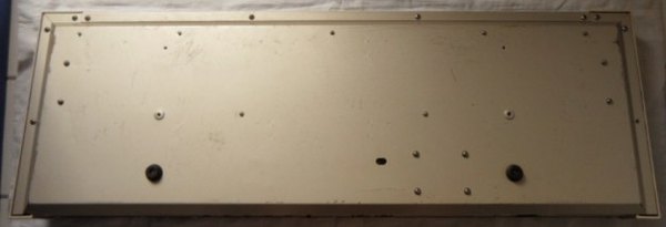
| removal of these screws voids warranty... | ||
 |
||
|
|